Industry Projects
Mechanical Projects NPP Equipment
Upper Block CPS
Internship Program-Project Program-Product Dev, Program


UNIT I
Four Exmples from Text Book will be given trainingOn software listed For the program Four problem will be given for self training with software to Trainee
This section presents the results of the calculation for seismic resistance of the upper block and drives of the CPS of the SHEM-M type.
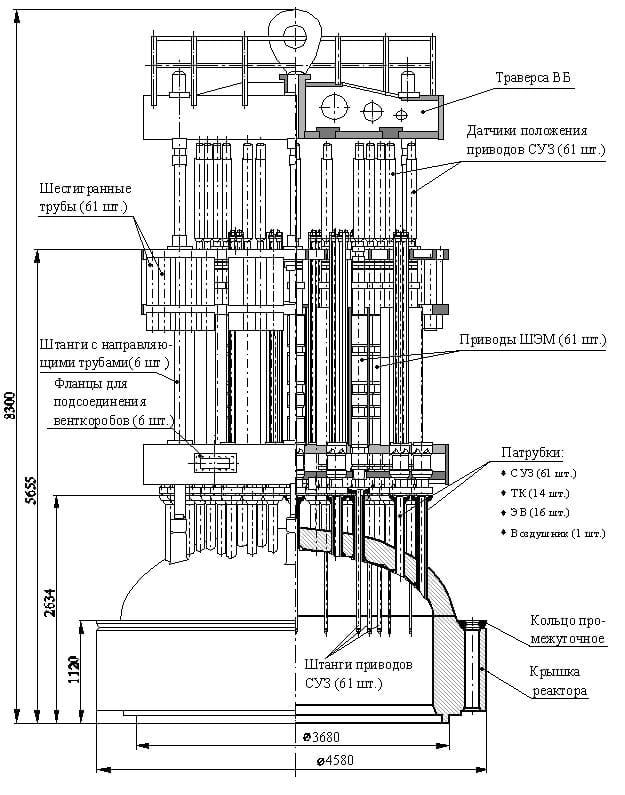
In the upper block (WB) of the VVER-1000 reactor there are CPS, the working body (ER) of which is the absorbing rods of the control and protection system (CPS PS), designed to quickly terminate the nuclear reaction in the core, maintain the reactor power at a given level and its transition from one level to another.
Structurally, the upper block consists of a crosshead with spacer grids, mounted on 6 racks. The struts are rigidly fixed to the reactor vessel.
Spacer grids (both upper and lower) are diaphragms with holes, into the holes of which stepping electromagnetic (SEM) drives of protection rods are inserted. With the help of these drives, the protection rods are controlled (they are raised and lowered).
In emergency mode, the devices of the Emergency Response Plant are de-energized, and under the influence of their own weight, internal rods with protection rods are inserted into the reactor core and stop the nuclear reaction.
Seismic resistance calculations were carried out in accordance with the requirements of PNAE G-7-002-86, "Strength Design Standards for Equipment and Pipelines of Nuclear Power Plants".
Also, when carrying out the work, the recommendations given in the following IAEA documents were taken into account:
«Seismic Design and Qualification for Nuclear Power Plants» Safety Standards Series №NS-G-1.6, IAEA, Vienna. 2003;«Evaluation of Seismic Safety for Existing Nuclear Installation» Safety Standards Series №NS-G-2.13, IAEA, Vienna, 2009;«Seismic Evaluation of Existing Nuclear Power Plants», Safety Reports Series № 28, IAEA, Vienna, 2003.
Based on the recommendations of the IAEA materials listed above, the analysis of seismic resistance of equipment and pipelines is carried out by the seismic boundary test (EASC).
The calculation was carried out in the APM WinMachine software product.
UNIT IV
Four Exmples from Text Book will be given trainingOn software listed For the program Four problem will be given for self training with software to Trainee
As part of the work, the seismic resistance of the upper block and drives of the CPS of the SHEM-M type was assessed.
As an expert-level earthquake (SEI) for the calculations, a seismic action with a maximum acceleration on a free surface ZPA = 0.12g was taken.
The strength of the upper block was assessed in accordance with the requirements of PNAE G-7-002-86, which showed that all elements of the upper block considered in this report meet the strength criteria under the combination of NOE+MRZ loads.
Based on the calculations for seismic impact, the values of the boundary seismic resistance HCLPF and the values of the seismic margin were obtained.
The minimum value of the seismic boundary level of the upper block is HCLPF= 0.22g.
The minimum seismic margin is 89%.

UNIT II
Four Exmples from Text Book will be given trainingOn software listed For the program Four problem will be given for self training with software to Trainee
In accordance with IAEA recommendations, the analysis of seismic resistance of NPP equipment and pipelines in operation is carried out using the seismic boundary resistance (MAP) method.
In accordance with PNAE G-5-006-87, CPS drives must be designed for a combination of NURE and NURE + MRZ loads.
Loads on the EO elements in the NEE mode will be due to the action of gravity only, and seismic forces will be added to them in the NEE + MRP mode.
The seismic stability assessment was performed using seismic action with a maximum peak acceleration of 0.12g.
In the calculation, the value of relative damping was assumed to be 2% relative to the critical one.
Calculation model
The calculation model was created on the basis of the drawings of the upper block. The upper reactor block is installed vertically, the lower support of which is the upper cover of the reactor. All this suggests that both the racks of the upper block and the CPS rods have supports in the form of seals, in which the reactions will be not only in the form of forces, but also in the form of moments.
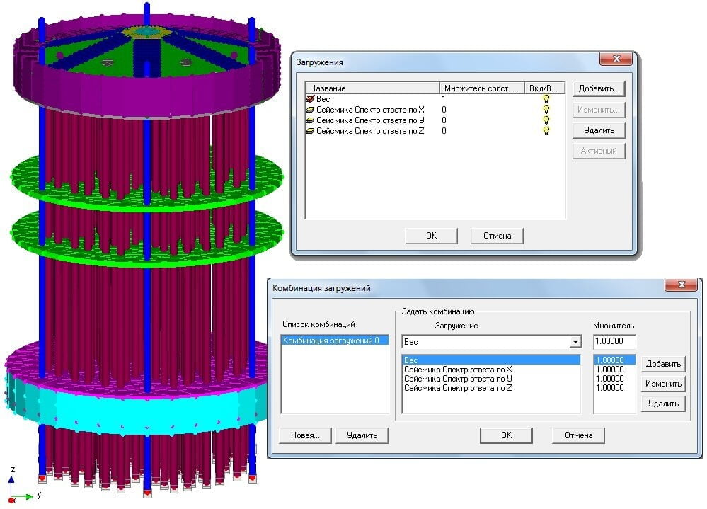
The computational model includes all the main elements of the EB - the crosshead, spacer grids and SEM rods. When building the analysis model in the APM Structure3D module, a final shell element was used for the crosshead, distance grids, etc. The struts, as well as the SEM rods, were modeled using rod finite elements, of the "beam" type. To ensure the possibility of axial displacement of the SEM rods in the distancing grids, the release of ties in the axial direction in the common node connecting these bars with the lattice nodes was used.
Since the holes in the spacer grid only guide the CPS rods, allowing them to shift in the axial direction and preventing its radial movements, this circumstance should be taken into account in the model.
UNIT III
Four Exmples from Text Book will be given trainingOn software listed For the program Four problem will be given for self training with software to Trainee
The seismic analysis was carried out by the linear-spectral method, taking into account the different number of natural frequencies used in different oscillation directions. For example, if when calculating the oscillations in the X and Y planes, it was enough to take into account the first 21 eigenforms, then for the correct accounting of the seismic impact according to Z, it was necessary to take into account the first 382 eigenforms in order to provide the sum of modal masses in each of the directions of at least 90%.
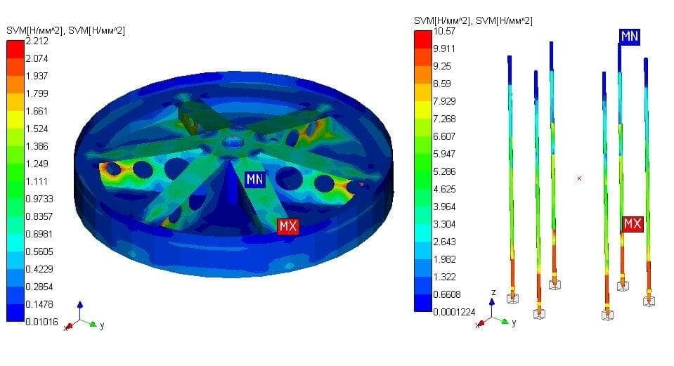
The calculation results are presented in the form of reduced stresses at NEE and the combination of NEE + MRP in the elements of the upper block with CPS drives with an indication of the maximum values.