Industry Projects
Construction Projects
Bridge Structure River Bridge
Internship Program-Project Program-Product Dev, Program


UNIT III
Four Exmples from Text Book will be given trainingOn software listed For the program Four problem will be given for self training with software to Trainee
UNIT I
Four Exmples from Text Book will be given trainingOn software listed For the program Four problem will be given for self training with software to Trainee
The Russian Ecological Fund "TECHECO" was established to implement programs for the environmental, financial, economic, industrial and technical safety of enterprises and organizations.
By order of the TECHECO organization, a strength analysis of the bridge supports over the Desna River was carried out.
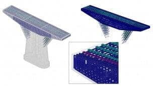
The construction of models and the entire complex of calculations were carried out using the APM Structure3D calculation module.
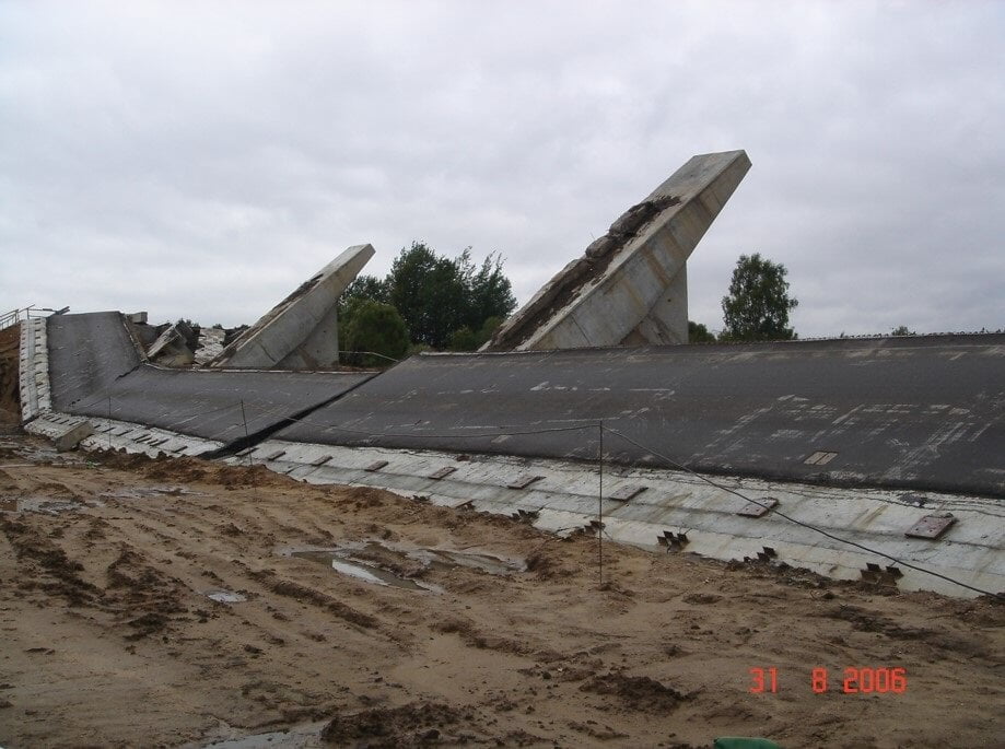
In the process of reconstruction of the bridge, at a certain stage of dismantling the old span beams, it was destroyed. The main task was to consider and analyze the behavior of both individual supports and the bridge as a whole, at different stages of dismantling the spans on the right side of the bridge, in accordance with the completed work schedule.
UNIT IV
Four Exmples from Text Book will be given trainingOn software listed For the program Four problem will be given for self training with software to Trainee
A significant amount of fatigue resistance margin is associated with the practical absence of cyclic load in this area of the wheel.
Wheels with a flat-conical disc with a ring defect (up to 20x5 in size) have sufficient static and fatigue strength, and the presence of an annular groove does not have a significant impact on the distribution of stresses in the wheel hub.
The work carried out showed the applicability of the APM WinMachine software package for solving complex problems of strength analysis of railway transport.
The work was done in full. The results obtained are reliable and confirmed by the real picture of the destruction of the bridge.
The work carried out showed the applicability of the APM Civil Engineering software package for solving complex problems of strength analysis and bridge expertise.

UNIT II
Four Exmples from Text Book will be given trainingOn software listed For the program Four problem will be given for self training with software to Trainee
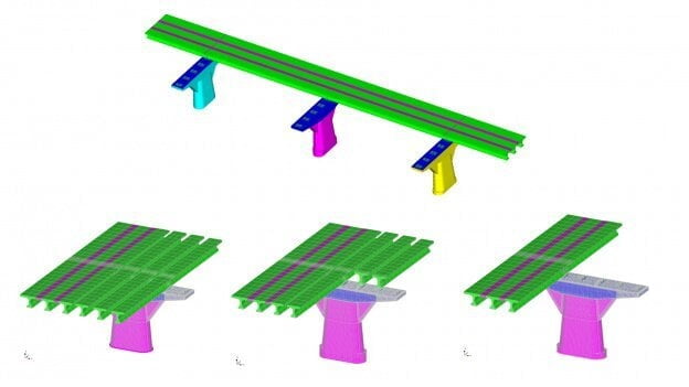
Within the framework of the given problem, the calculation of the fourth support, as well as the calculation of the part of the bridge, starting from the fourth support and ending with the ninth, is considered.
Two types of finite elements (FEs) are used to build the model: solid FE for concrete modeling and member FE for rebar modeling.
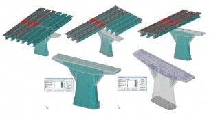
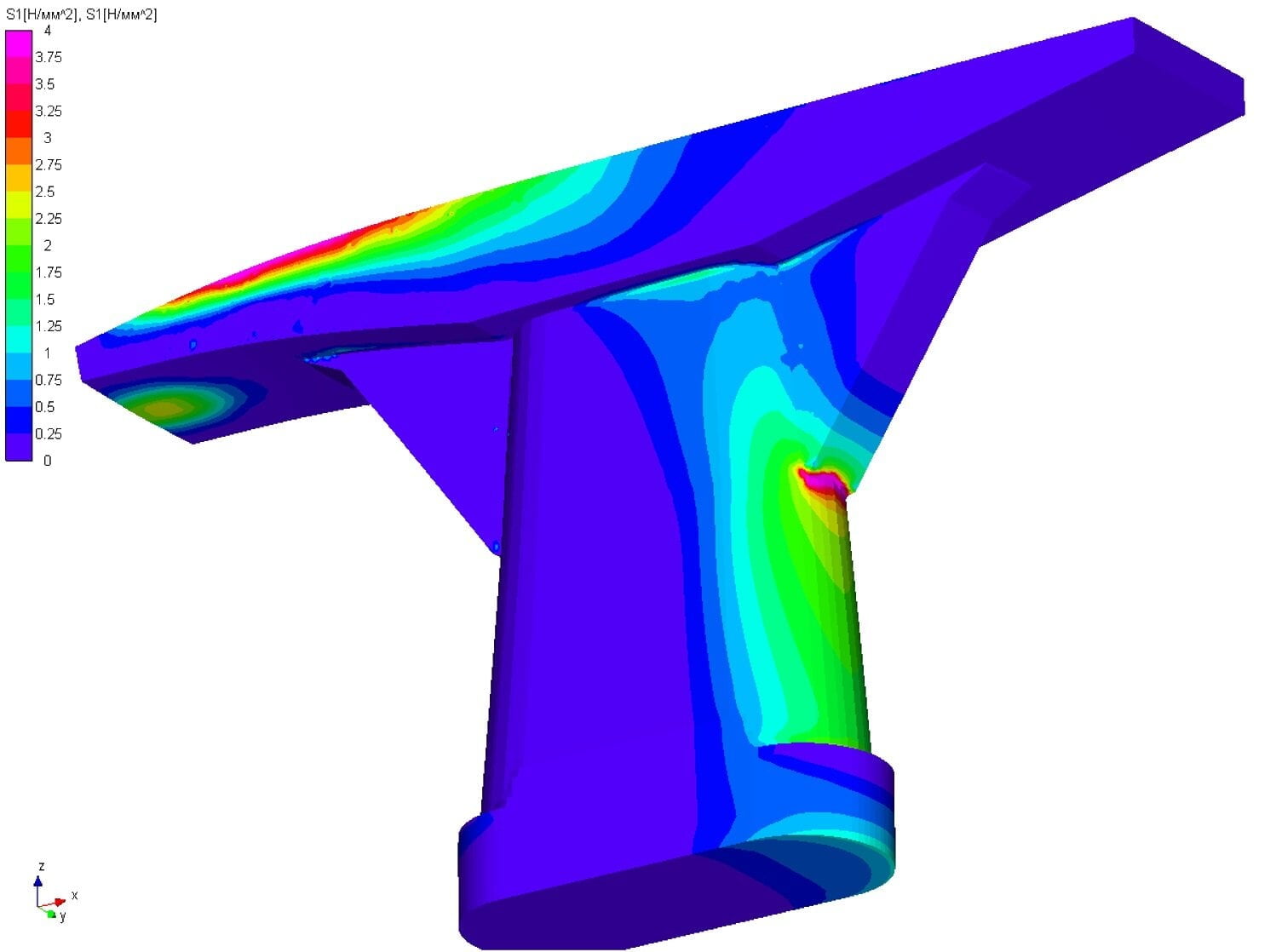
To obtain a reliable picture, the main stress distribution map S1 is best suited. Positive values of principal stresses will characterize the tensile zones.
From the result maps, there is a surge of tensile stresses at the junction of the rib and the support body. However, this burst is only the result of a docking site simulation error, characterized by a transition from an 8 to a 4 knot finite element. The actual level of operating stresses should be estimated on 2-4 layers of finite elements and will be a slightly lower value, about 10-15%.
In the calculation, the sequential opening of the joint in the area of the defect in the manufacture of the support due to significant tensile stresses is simulated.
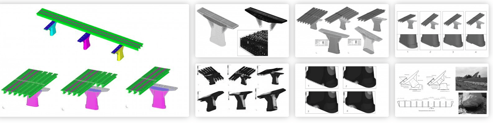
The model of three bridge supports as a single design scheme at the last stage of dismantling the old span beams of the right part of the bridge is also considered.
To simulate the interoperability of work with adjacent bridge elements, the right end of the span beams (the length of which is exactly half the real length of the beams) was fixed by prohibiting movement along the axis of the beams, thereby taking into account the presence of the adjacent support and span beams.