Industry Projects
Construction Projects
RCC Structure Nuclear Power Plant
Internship Program-Project Program-Product Dev, Program




UNIT III
Four Exmples from Text Book will be given trainingOn software listed For the program Four problem will be given for self training with software to Trainee
Loads on the RO building are accepted in accordance with the requirements of DBN V.1.2-2:2006, DBN V.1.1-12-201X, MT-T.0.03.326-13.
Seismic analysis is carried out in accordance with the requirements of DBN V.1.1-12-201X, MT-T.0.03.326-13.
The values of the strength characteristics of concrete and reinforcement were used, depending on the coefficient of working conditions, taking into account the features of the concrete and reinforcement in the structure. The coefficients of the working conditions of concrete and reinforcement are adopted on the basis of DSTU B V.2.6-156:2010.
The calculation took into account:
Constant loads
Own weight of load-bearing structures;The lateral pressure of the soil on the walls of the building is below the 0.000 mark.
Variable loads
1. Variable long-term loads
Stationary Equipment WeightFluid Pressure
2. Variable short-term loads
Snow loadWind Load
Occasional loads
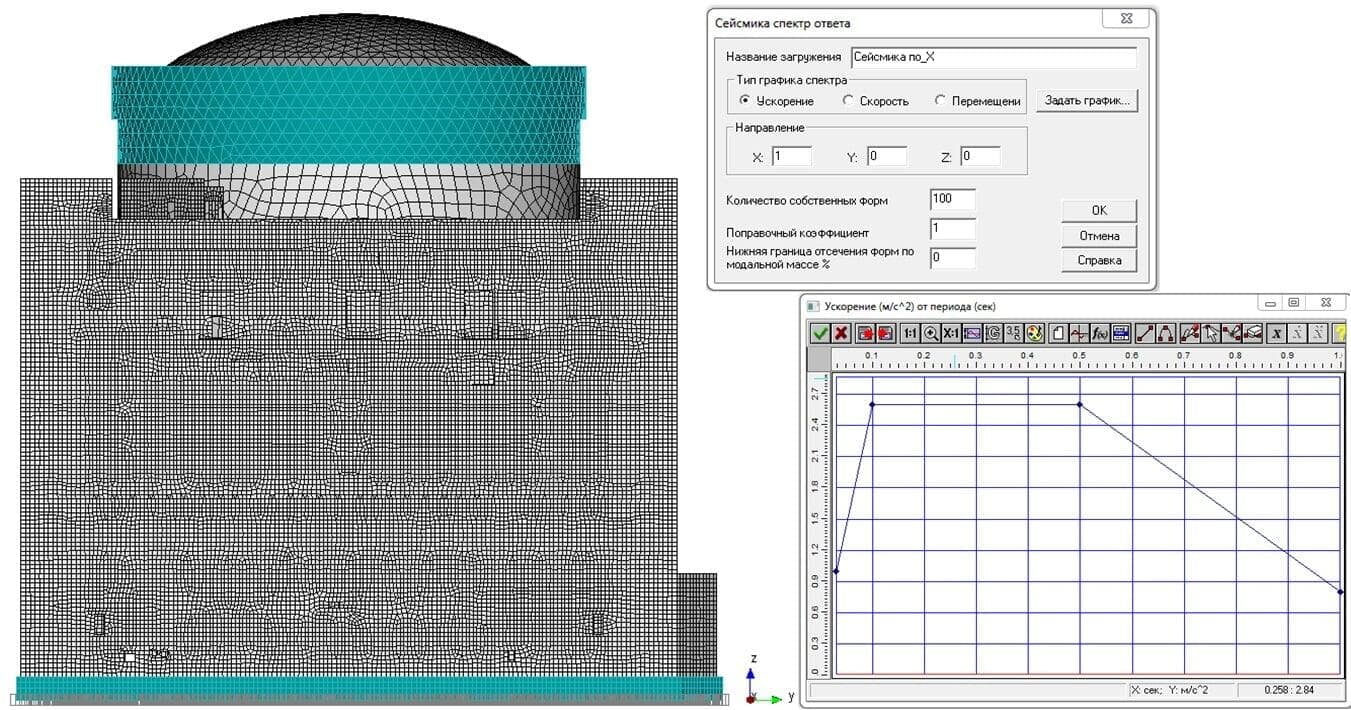
Episodic loads acting on the RO building include seismic impacts. The initial data for the calculation using the linear-spectral method are generalized response spectra (in this case, graphs of the dependence of the acceleration transmitted to the structure on the frequency of natural oscillations).
Load combinations for performing calculations for the first and second groups of limit states, as well as for calculating the HCLPF parameter (seismic boundary characteristic) are selected in accordance with the requirements of DBN V.1.2-2:2006, DBN V.1.1-12-201X, MT-T.0.03.326-13.
Verification of the limit states of the first group is carried out for an emergency combination of loads, including the limit design values of permanent, long-term and short-term variable loads, as well as loads from seismic impacts.
Verification of the limit states of the second group includes the calculation for the emergency combination, taking into account the operational design values of the loads.
Calculation model
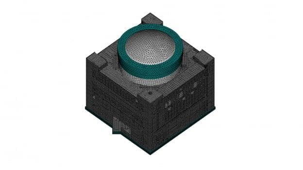
The calculation model of the RO building was built in accordance with the formwork working drawings received from the Customer.
Reinforcement of the load-bearing structures of the reactor compartment building is set in accordance with the reinforcing working drawings.
When building the design model for walls, floors, coating and foundation slab, four-node and three-node plate finite elements were used, for columns inside the hermetic volume – rod finite elements. When building the reactor shaft, voluminous four-node finite elements were used.
Force boundary conditions on the structure of the RO building are set in accordance with the requirements of regulatory documents.
Kinematic boundary conditions are defined as a hinge fastening of the foundation slab nodes.
UNIT I
Four Exmples from Text Book will be given trainingOn software listed For the program Four problem will be given for self training with software to Trainee
NPP Reactor Department Building
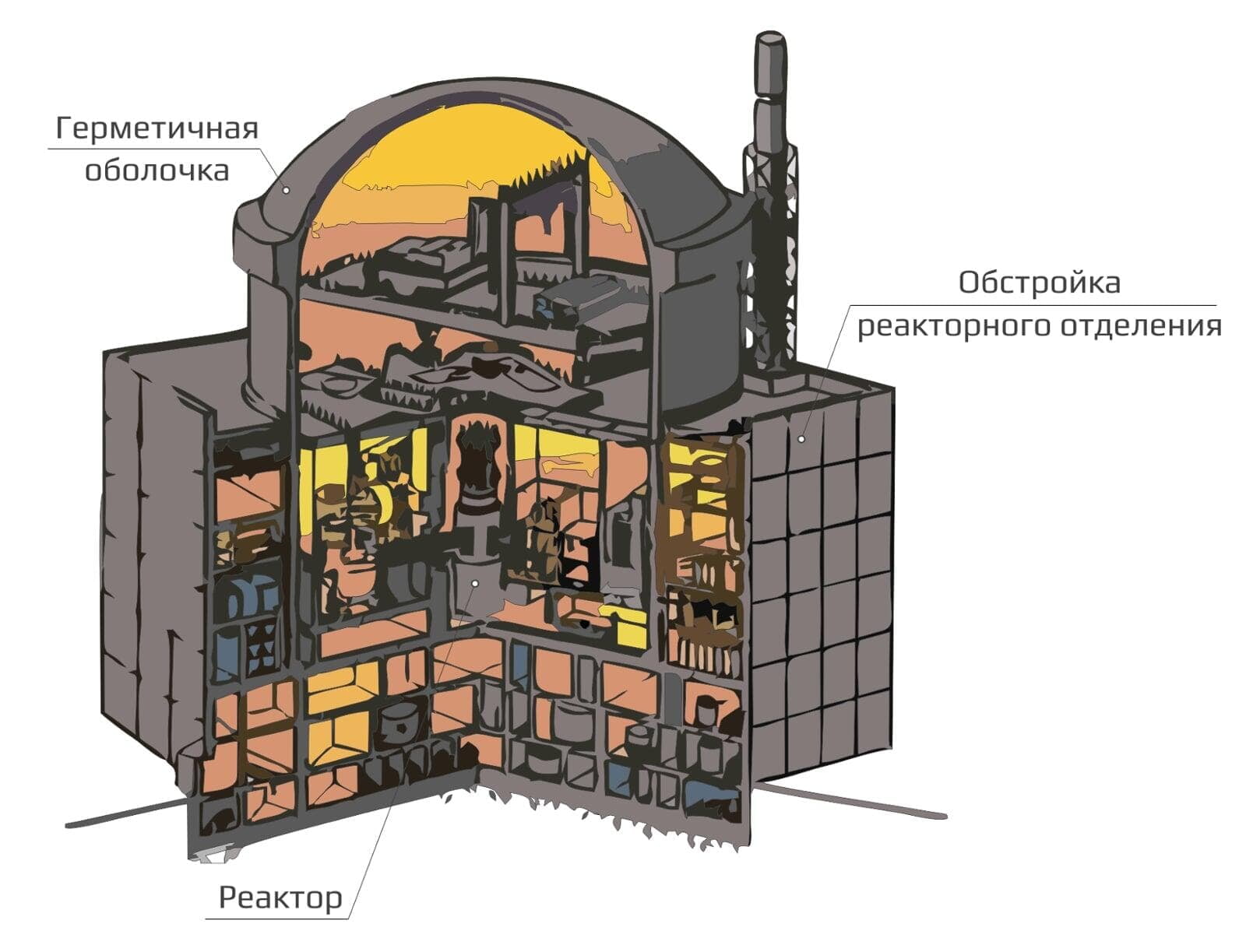
The reactor building is a monolithic reinforced concrete structure. The building includes an outbuilding located around a sealed containment and the hermetic containment itself. The structures of the outbuilding are separated from the hermetic protective shell by a deformation joint.
The RO outbuilding is a multi-storey structure made of prefabricated monolithic reinforced concrete. A monolithic reinforced concrete slab was adopted as the foundation of the building. The external and internal walls of the outbuilding are made of prefabricated monolithic reinforced concrete: factory-made external block-cells, serving as a permanent formwork and monolithic reinforced concrete laid between them. The intermediate floors are made of monolithic and prefabricated monolithic reinforced concrete. Floors and walls form a rigid connection by ensuring the length of the reinforcement anchoring.
At a certain level, there is a monolithic reinforced concrete slab in the outbuilding, which, together with the foundation and overlying walls, forms a rigid box-shaped structure - a stylobate, which serves as the basis for a sealed protective shell.
The protective shell is a sealed volume consisting of a vertical reinforced concrete cylindrical part and a spherical (ball) prestressed dome. The protective shell is installed on a monolithic reinforced concrete stylobate. The connection between the sealed protective shell and the stylobate is rigid.
Foundation part (stylobate)
The foundation part of the building includes the stylobate, which consists of the foundation slab itself, monolithic walls and ceilings rigidly connected to each other. The walls of the foundation part are structures made of monolithic reinforced concrete using non-removable formwork in the form of flat reinforced concrete slabs of factory production.
UNIT IV
Four Exmples from Text Book will be given trainingOn software listed For the program Four problem will be given for self training with software to Trainee
Seismic analysis is carried out by the linear-spectral method using the spectra of horizontal and vertical accelerations. The natural frequencies and the corresponding oscillation forms of the RO building were determined by the FEA. The number of natural frequencies taken into account in the calculation for seismic impacts was determined in accordance with the requirements of regulatory documents.
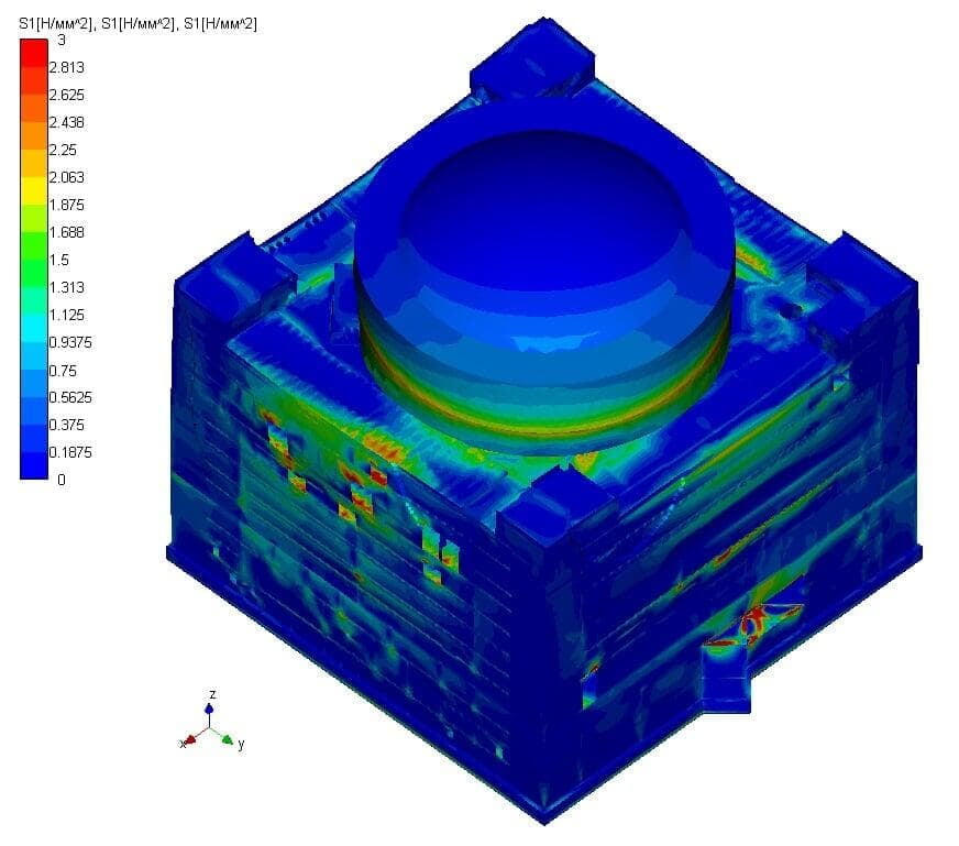
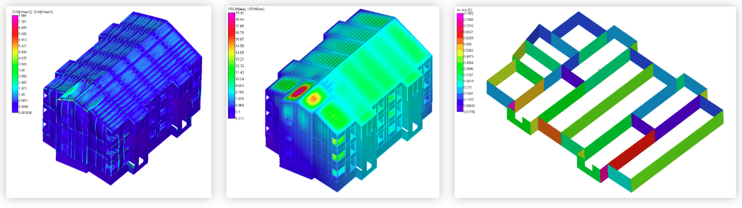
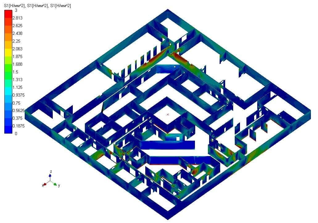
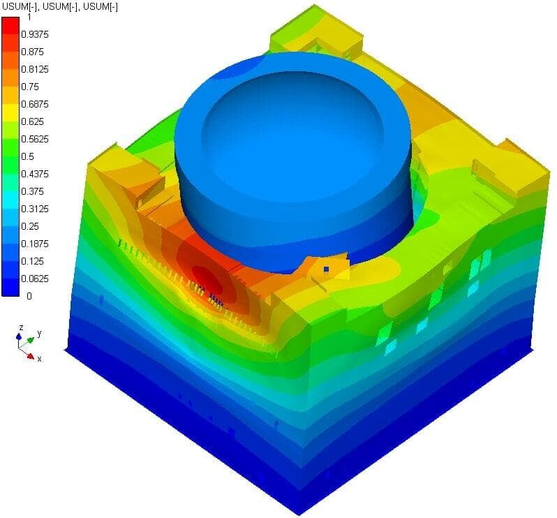
As a result of the calculation, the maximum main tensile stresses and vertical displacements of the RO building, as well as its elements, were determined.
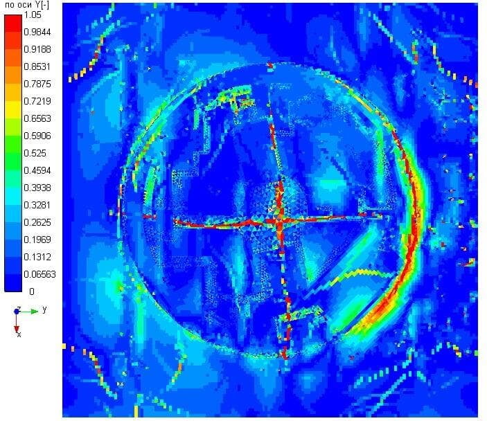
The calculation of the vertical and horizontal reinforcement of the walls for the first group of limit states for each elevation is carried out.
The calculation for seismic effects of the NPP reactor building was carried out. From the results of the calculations performed, it follows that the strength of the building of the RO NPP under seismic effects meets the requirements of DBN V.1.1-12-201X, MT-T.0.03.326-13 and DSTU B V.2.6-156:2010.
The work carried out showed the applicability of the APM Civil Engineering software package for solving complex problems of strength analysis of critical reinforced concrete structures.
UNIT II
Four Exmples from Text Book will be given trainingOn software listed For the program Four problem will be given for self training with software to Trainee
The foundation part of the building includes the stylobate, which consists of the foundation slab itself, monolithic walls and ceilings rigidly connected to each other. The walls of the foundation part are structures made of monolithic reinforced concrete using non-removable formwork in the form of flat reinforced concrete slabs of factory production.
Outbuilding structuresSlabs
The floors are made of monolithic and prefabricated monolithic, consisting of prefabricated ribbed shell slabs and monolithic reinforced concrete. For prefabricated monolithic floors, ribbed shell slabs serve as a permanent formwork.
Walls of the outbuilding
The walls of the outbuilding are monolithic and prefabricated monolithic structures consisting of prefabricated block cells and monolithic reinforced concrete laid between them.
Sealed Volume StructuresSealed Volume Overlap
The structures of the sealed volume are located inside the protective shell. The floors inside the sealed volume are made of monolithic reinforced concrete. The connection of the monolithic ceilings of the pressurized volume with the walls of the holding and reloading pool, the "wet" reloading shaft and the reactor shaft is rigid (due to ensuring the length of the reinforcement anchoring).
Walls of sealed volume
The walls of the sealed volume rest on the stylobate structure and are rigidly connected to it. Sections of the walls inside the sealed volume are lined with hot-rolled carbon steel sheets.
Holding & Overload Pool
The spent fuel and wet transfer pool is a monolithic reinforced concrete shaft. The shaft consists of four combined cells, which together with the reactor shaft form a rigid reinforced concrete structure.
The tightness of reinforced concrete structures is ensured by the arrangement of external and internal cladding with steel sheets. The inner surface of the walls and bottom is additionally lined with stainless steel sheet with a thickness. The stainless steel cladding is rigidly connected to the carbon steel cladding by welding to the embedded parts.
Wet Overload Shaft
The "wet" overload shaft is a monolithic reinforced concrete structure located on a stylobate.
Reactor shaft
The reactor shaft is a cylindrical monolithic reinforced concrete structure. The walls of the reactor shaft are lined with carbon steel sheets, which were used as permanent formwork. The design of the shaft provides protection of power equipment from the effects of emergency and seismic loads, and also provides biological protection in all operating modes.
The calculation of the building was carried out in accordance with:
Reference manual "Design of retaining walls and basement walls" to SNiP 2.09.03-85 "Construction of industrial enterprises".DBN V.2.1-10-2009 "Bases and foundations of buildings and structures".DBN V.1.2-2:2006 "Loads and Impacts. Design Standards".NUREG/CR-0098 «Development of criteria for seismic review of selected nuclear power plants».DBN V.1.1-12-201X "Construction in seismic regions of Ukraine".MT-T.0.03.326-13 "Method of Computational Analysis of Seismic Resistance of Elements of Operating NPPs within the Framework of the Seismic Boundary Resistance Method".DSTU B V.2.6-156:2010 "Concrete and reinforced concrete structures made of heavy concrete. Design Rules".DBN V.2.6-198:2014 "Steel structures. Design Standards".
The purpose of the calculation is to carry out the analysis for seismic effects.
The calculation was carried out in the APM CivilEngineering software product.