Industry Projects
Construction Projects
Transculant Structure Canopy Structure
Internship Program-Project Program-Product Dev, Program

UNIT III
Four Exmples from Text Book will be given trainingOn software listed For the program Four problem will be given for self training with software to Trainee
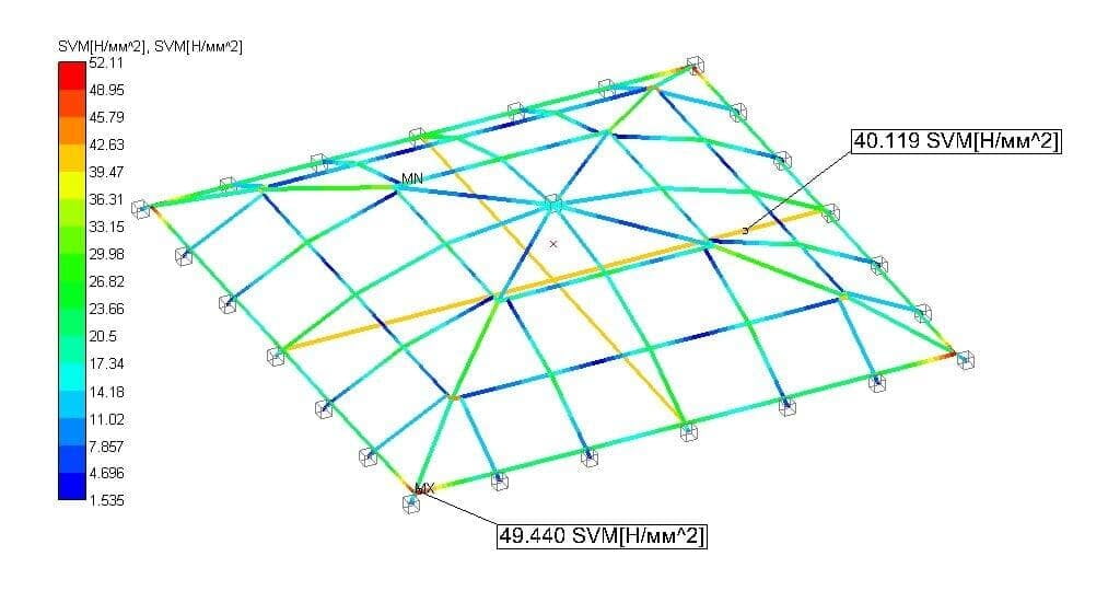
A static calculation of the structure for the main load combinations was performed. Maps of the stressed and deformed state of the structure were obtained.
Deflections are determined according to SP 20.13330.2011.
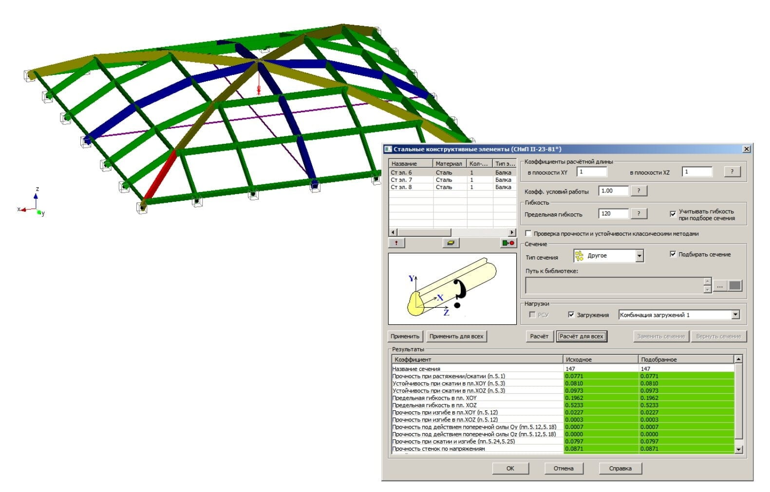
According to SNiP II-23-81*, the bearing capacity of the most loaded structural elements was checked.
UNIT I
Four Exmples from Text Book will be given trainingOn software listed For the program Four problem will be given for self training with software to Trainee
The strength calculation of the metal structure of the canopy for the main combination of loads was carried out.
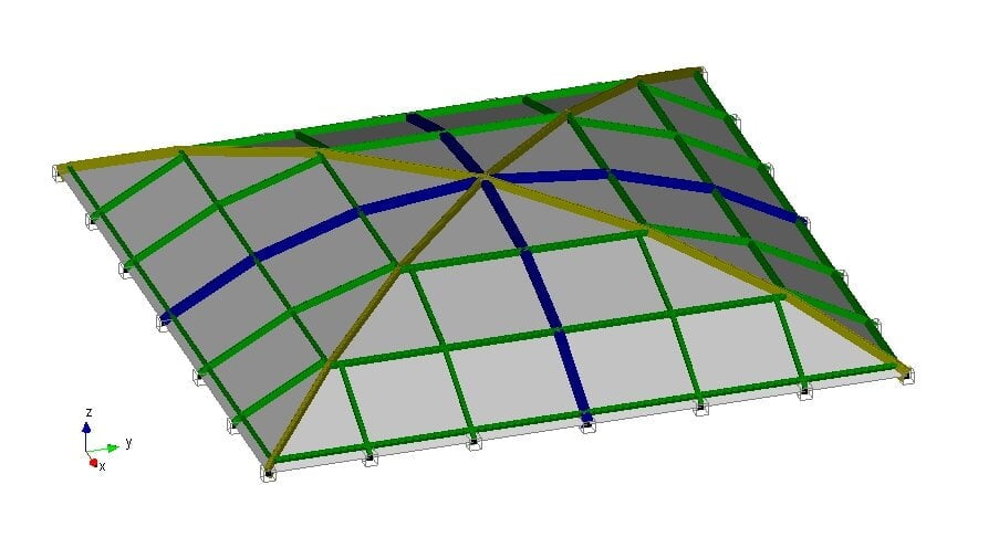
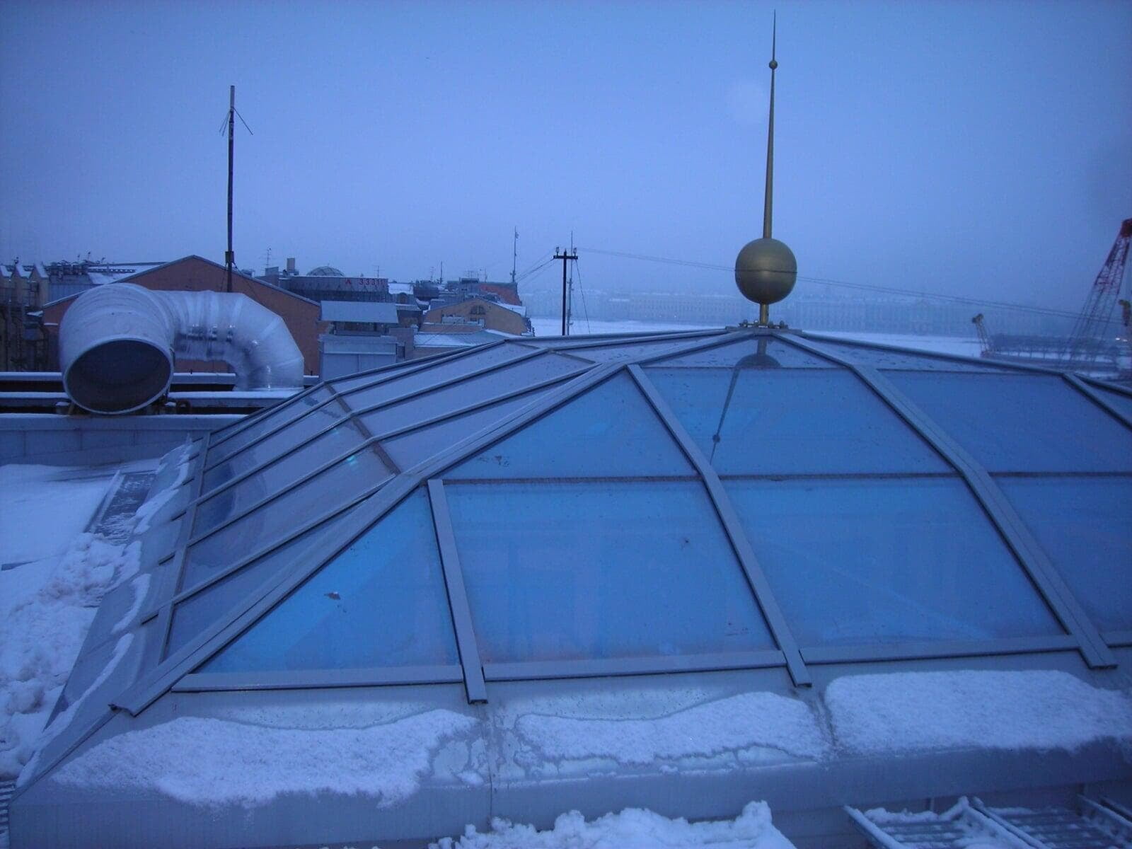
Geometric dimensions of the model: length 6000 mm, width 6000 mm, height 1100 mm. The frame is made of a façade profile of different heights.
The metal structure rests on the frame of the building. The joints of the metal structure units are rigid welded along the contour.
The design analysis was carried out according to:
SP 20.13330.2011 Loads and Impacts. Updated edition of SNiP 2.01.07-85.SNiP II-23-81* Steel structures.
The calculation was carried out in the APM CivilEngineering software product.
UNIT IV
Four Exmples from Text Book will be given trainingOn software listed For the program Four problem will be given for self training with software to Trainee
A static calculation of the structure for the main combination of loads was carried out, as well as a check of the bearing capacity according to SNiP II-23-81* "Steel Structures" for the most loaded structural elements.
Analysis of the results of the static calculation shows that at the specified design loads, the equivalent stresses arising in the structural elements when using the specified cross-sections do not exceed the yield strength of the materials used (design resistance), i.e. the required strength is provided. In the most unfavorable case of loading, the safety coefficient for the yield strength is greater than one and is equal to 4.4
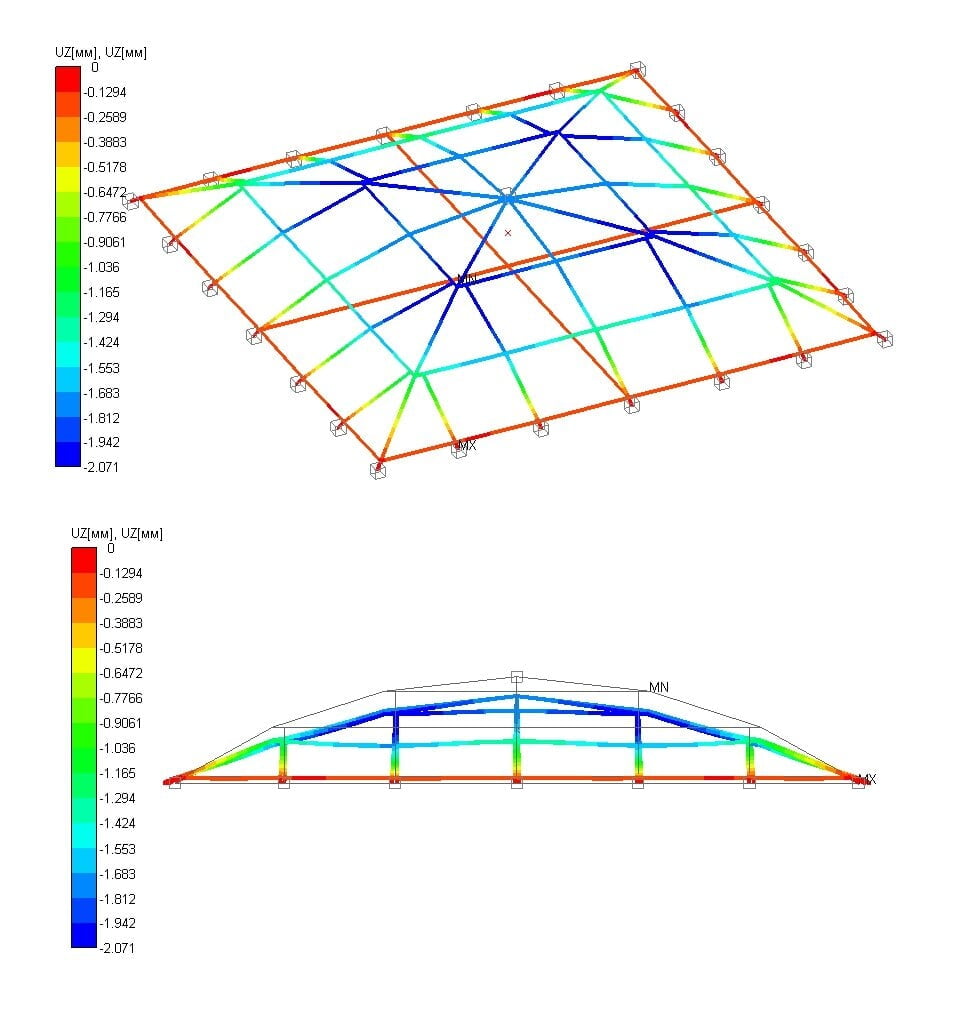
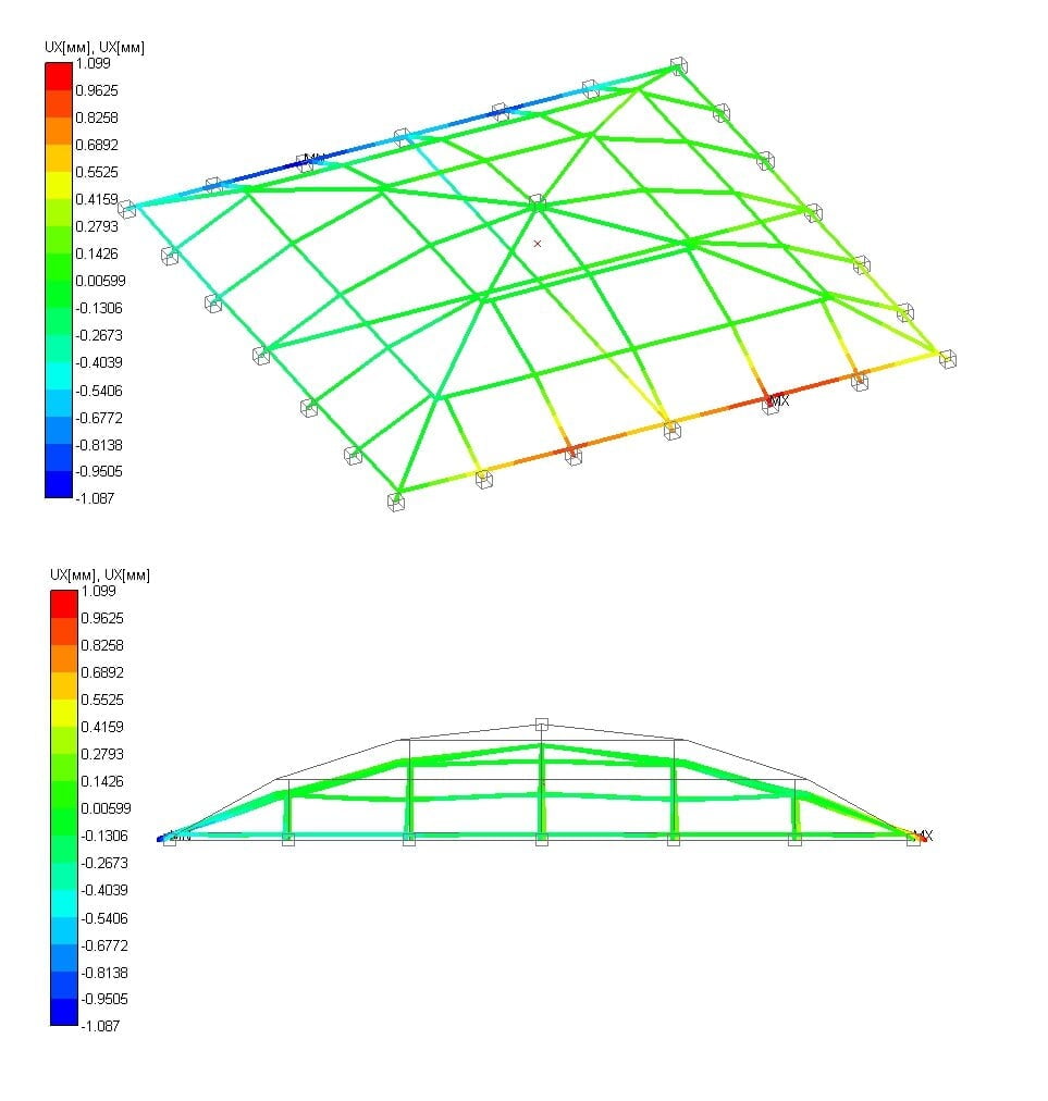
The maximum deflections of the structure, resulting from the combination of its own weight and external loads, do not exceed the permissible limit. That is, the necessary rigidity of the load-bearing frame is ensured.
Summarizing the results obtained, it can be concluded that the structure of the building is able to bear the loads applied to it, corresponding to the construction area, and does not require additional measures to increase the strength characteristics.
The work carried out showed the applicability of the APM Civil Engineering software package for solving complex problems of strong translucent structures.

UNIT II
Four Exmples from Text Book will be given trainingOn software listed For the program Four problem will be given for self training with software to Trainee
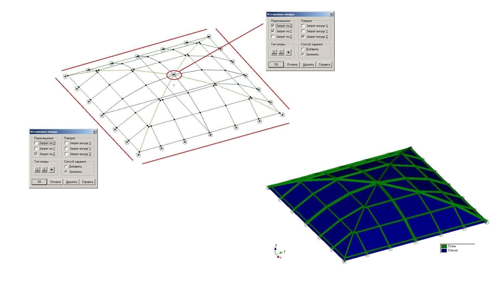
The design model of the building is built on the basis of drawings submitted by the customer.
The glazing was modeled with plates without rigidity.
Support constraints introduced during the calculation:
For the central point, the horizontal movement (X and Y) is prohibited - based on the symmetry condition of the structure. In addition, a full hinge is installed at the central point to account for possible movements in the connection.For control points, only the prohibition of vertical movement along the Z.
Supports are installed based on the global coordinate system axes of the editor.
Snow loads were determined in accordance with SP 20.13330.2011 (SNiP 2.01.07-85*).
The weight of the structure is taken into account with a premium of 5%. This figure corresponds to the load safety factor for the weight of building metal structures according to SP 20.13330.2011.
The weight of the spire is allocated in a separate load case. The load safety factor for the capstan structure is 1.2.
The calculation of the metal structure is carried out for the main combination of loads, taking into account the reliability factor by load and by responsibility.
Static analysis is carried out in the module for calculating the stress-strain state, stability, natural and forced vibrations of parts and structures using the finite element method - APM Structure3D, which is part of the APM Civil Engineering system for computer-aided analysis and design of structures for industrial and civil construction.