Industry Projects
Mechanical Projects Lifting and Conveying Equipment
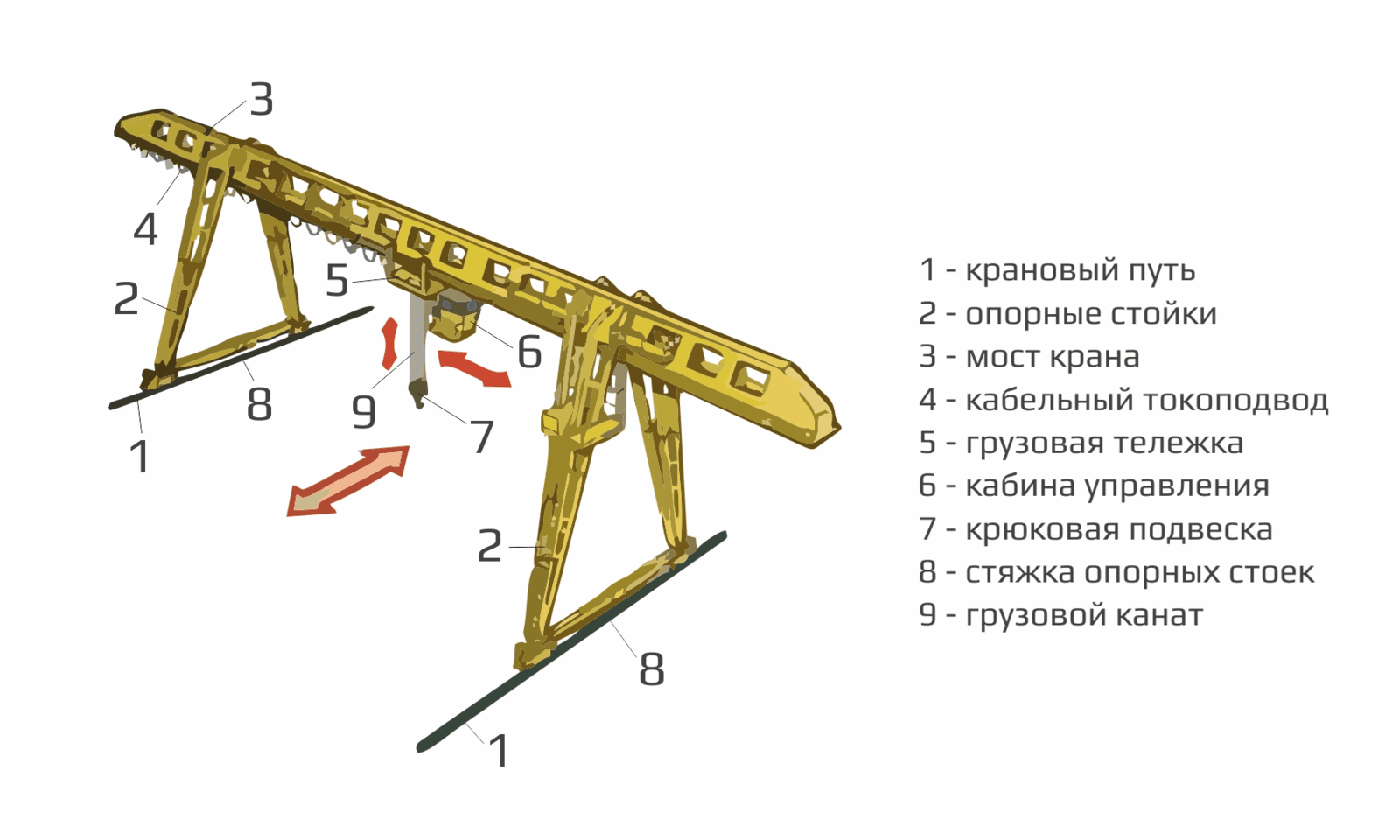
Gantry Crane
Internship Program-Project Program-Product Dev, Program



UNIT I
Four Exmples from Text Book will be given trainingOn software listed For the program Four problem will be given for self training with software to Trainee
Specialists of the company STC "APM" performed a strength calculation of the metal structure of the gantry crane.
The purpose of the calculation is to analyze the crane structure for strength, rigidity and stability under the action of design loads.
The calculation was carried out according to the requirements:
SNiP 2.01.07-85* Loads and Impacts.GOST 1451-77* (2003) Lifting cranes. Wind load. Norms and method of determination.SNiP II-23-81* Steel structures.
The calculation was carried out in the APM Civil Engineering software product.
UNIT IV
Four Exmples from Text Book will be given trainingOn software listed For the program Four problem will be given for self training with software to Trainee
4 static structural calculations have been performed for the main load case combinations.
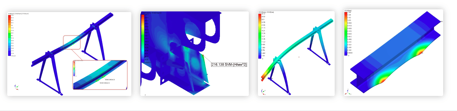
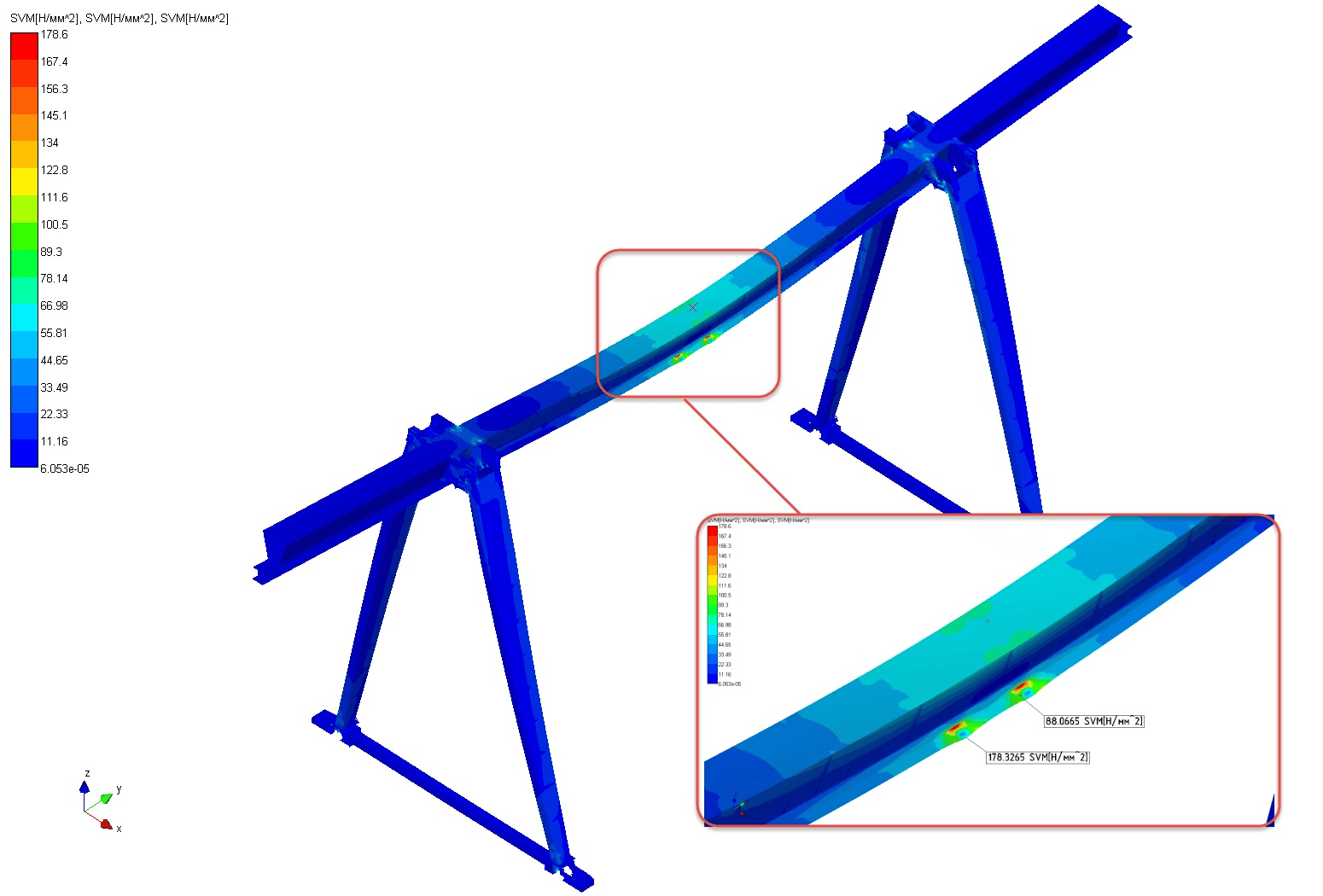
The maximum stresses in the structure of the gantry crane, when the trolley is centrally located, occur in the lower flange of the bridge girder (in the area where the load from the trolley is applied).
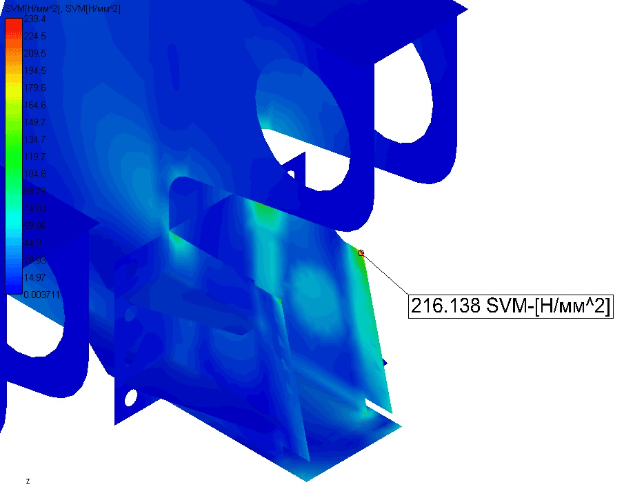
The maximum stresses in the structure of the gantry crane, with the cantilever arrangement of the trolley, occur in the rib of the support leg bracket (in the area of docking with the support leg).
In accordance with SNiP 2.01.07-85, the vertical limit deflections of the bridge beam are determined.
The load-bearing capacity of the crane bridge beam during the movement of the cargo trolley is evaluated separately.

UNIT II
Four Exmples from Text Book will be given trainingOn software listed For the program Four problem will be given for self training with software to Trainee
Calculation model
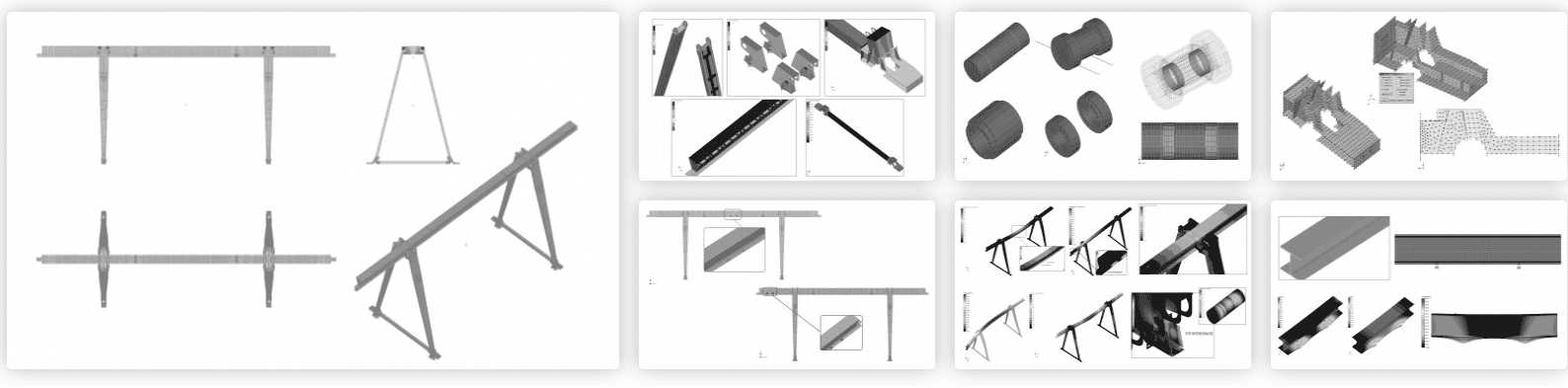
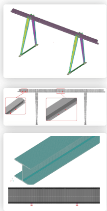
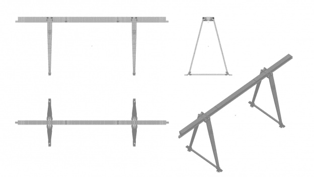
The design model of the load-bearing metal structure and the I-beam of the gantry crane bridge was formed on the basis of the documentation sent by the Customer.
The structural elements were modeled with plate and rod end elements.
The hinge connection of the gantry crane rack to the bridge was modeled using "sliding" type contact elements.
The metal structure of the gantry crane rests on rails, while a ban on all movements is established.
The weight of the structure is taken into account with a premium of 5%. This figure corresponds to the load reliability factor. The static load acting on the gantry crane is composed of the weight of the cargo trolley, the weight of the cargo and the weight of the hook suspension.
Analysis of the results of the static calculation showed that at the specified design loads, the equivalent stresses arising in the structural elements of the gantry crane do not exceed the yield strength of the materials used, i.e. the required strength is provided.
The maximum deflections of the gantry crane structure arising from external loads also do not exceed the permissible limit. That is, the necessary rigidity of the load-bearing frame is ensured.
Checking the load-bearing capacity of the most loaded structural element (the lower flange of the bridge beam) on a solid model showed that the stresses and displacements occurring in the
UNIT III
Four Exmples from Text Book will be given trainingOn software listed For the program Four problem will be given for self training with software to Trainee
in the center of the bridge;cantilever in the extreme possible position of the cargo trolley.
For a refined calculation of the lower flange of the bridge beam, a solid model of a 2 m long beam section was constructed.
In the model under consideration, the extreme ends of the beam are pinched, i.e. all displacements and rotations around all axes are prohibited, which, according to the Saint-Venant principle, does not have a significant impact on the picture of the stress-strain state in the local section of the structure remote from the supports.
The load from the cargo trolley is applied to the upper surface of the lower flange of the bridge beam on 4 platforms of size (along and across the beam, respectively). In this case, the size of the force application platform corresponds to the size of the contact zone that occurs when the freight trolley moves along the lower flange of the I-beam.