Industry Projects
Construction Projects
Structural Steel Mercedze Benz
Internship Program-Project Program-Product Dev, Program



UNIT I
Four Exmples from Text Book will be given trainingOn software listed For the program Four problem will be given for self training with software to Trainee
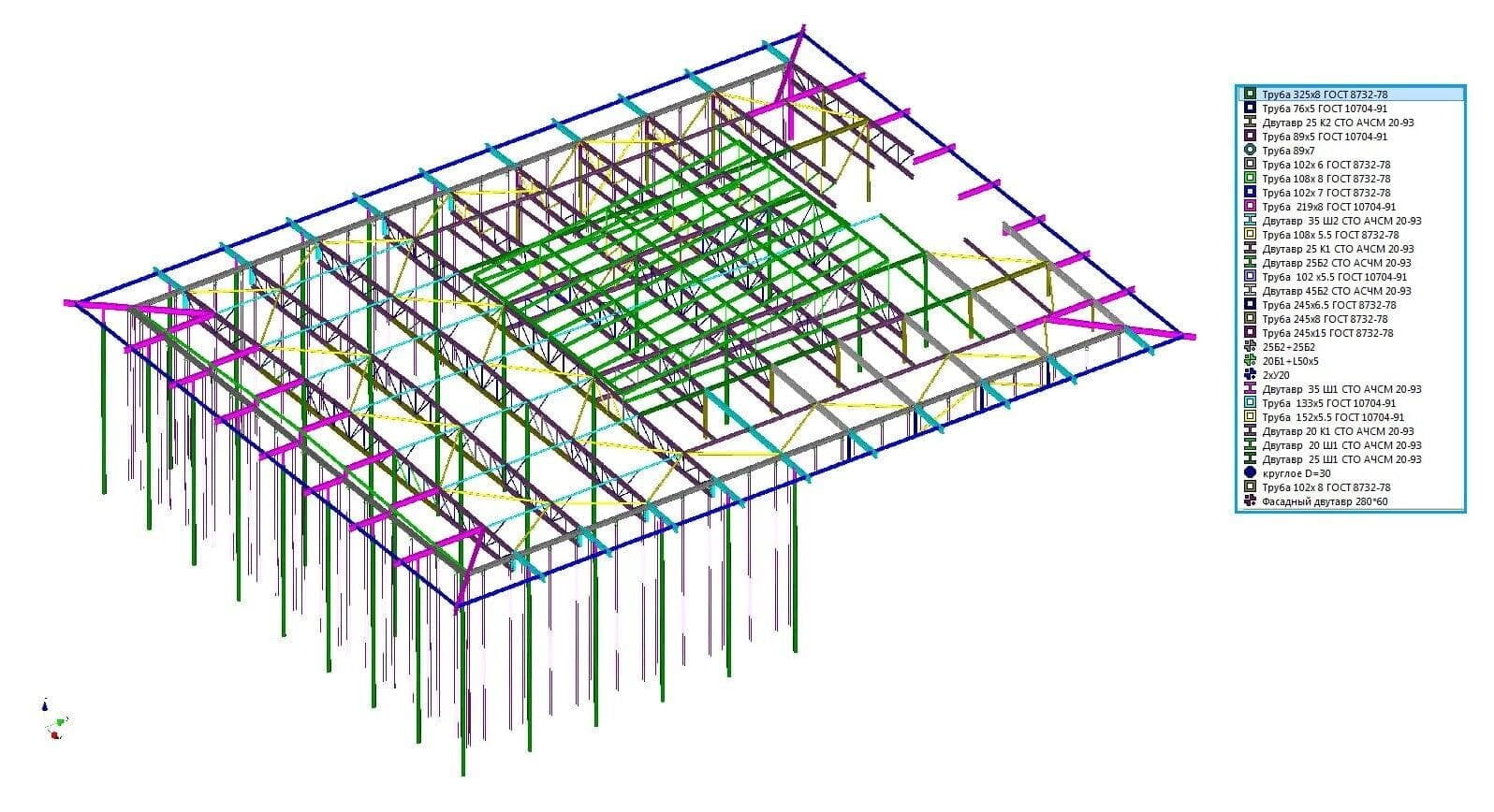
Calculation of the MERCEDES-BENZ Motor Exhibition Center in the APM Civil Engineering Software Package
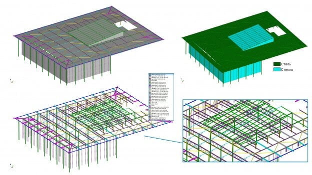
Geometric dimensions of the structure:
height: 15,450 mm;length: 67,300 mm;Width: 52,300 mm.
The calculation was carried out in accordance with:
SP 20.13330.2011 Loads and Impacts. Updated edition of SNiP 2.01.07-85.SP 16.13330.2011 Steel structures. Updated edition of SNiP II-23-81*.
The design analysis was performed in the APM CivilEngineering software product.
UNIT IV
Four Exmples from Text Book will be given trainingOn software listed For the program Four problem will be given for self training with software to Trainee
Calculation of the MERCEDES-BENZ Motor Exhibition Center in the APM Civil Engineering software package.
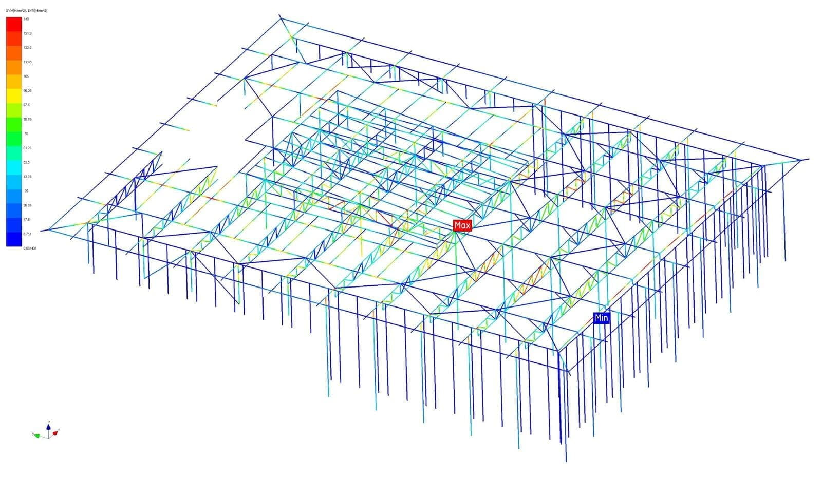
The analysis of the results of the static calculation showed that at the specified design loads, the equivalent stresses arising in the structural elements do not exceed the yield strength of the materials used (design resistance), i.e. the required strength is provided.
The maximum deflections of the center structure arising from the combination of temporary loads do not exceed the permissible limit determined according to SNiP 2.01.07-85*. That is, the necessary rigidity of the load-bearing frame is ensured.
Stability (extreme flexibility) along the glazing is provided by horizontal braces, as well as by the glazing itself.
Summarizing the results obtained, it can be concluded that the structure of the auto exhibition center is able to bear the loads applied to it, corresponding to the area of operation, and does not require additional measures to increase strength characteristics.
UNIT II
Four Exmples from Text Book will be given trainingOn software listed For the program Four problem will be given for self training with software to Trainee
The initial data are provided by the working documentation of stage P.
Area of construction of the center:
according to the maps of snow loads: district III;according to wind load maps: District II;type of area of operation - A according to GOST R 52170-2003.
The metal structure of the auto exhibition center is attached to the previously built foundation.
Calculation model
The design model was built on the basis of drawings submitted by the customer. The design of the exhibition center was modeled by rod-plate elements.
Design loads on the center structure include:
weight of the structure;snow load;wind load in two directions.
The model does not take into account the weight of fasteners, as well as welded bolt and flange connections, so the weight is taken into account with a premium of 10% (the self-weight multiplier is assumed to be equal to 1.1).
The construction site of the auto exhibition center according to SP 20.13330.2011 (SNiP 2.01.07-85*) belongs to the III snow region, so the snow load is taken into account according to the above document.
Wind counting was carried out for two directions of wind action: perpendicular and parallel to the long side of the building. When determining the wind load, the corresponding values of aerodynamic coefficients were used.
UNIT III
Four Exmples from Text Book will be given trainingOn software listed For the program Four problem will be given for self training with software to Trainee
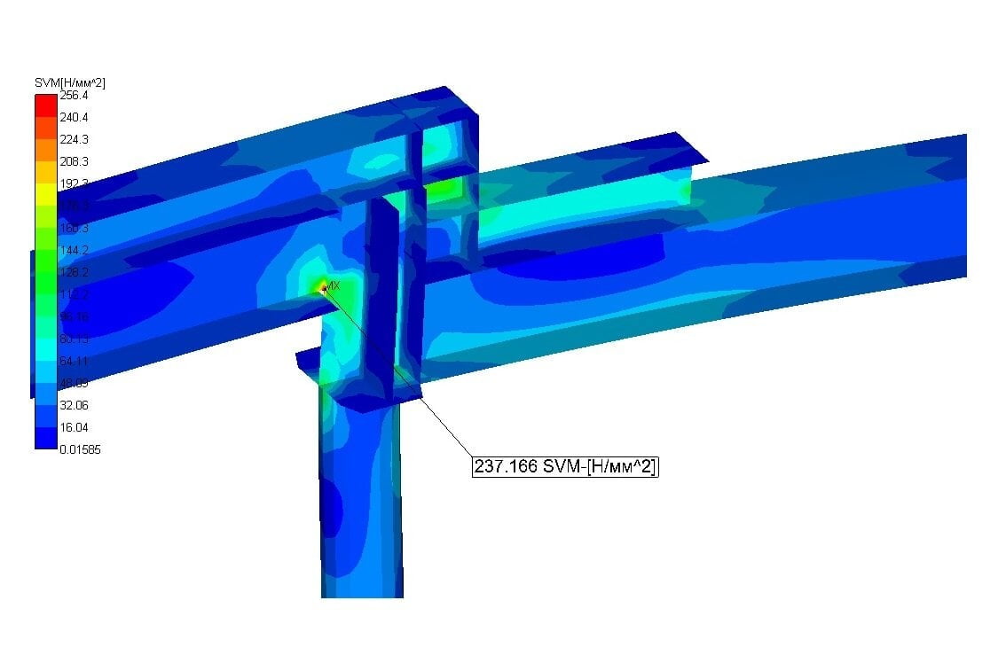
The ultimate flexibility of the truss elements has been checked. Truss node forces, shear forces, Misis stresses, and bending moments are determined.
Within the framework of the project, a static design of the structure for the main load combinations was carried out for four design cases (load case combinations). Maps of the stressed and deformed state of the structure under the corresponding load variants are obtained.
Structural elements were checked according to SNiP II-23-81*, and the stability of the structure was assessed.
In addition, the strength of the truss support unit on the column was analyzed, while the load from the half-timbered racks was taken into account.