Kompas 3D Mechanical Application I
Women Graduates are trained with basics in Industry application from basic science Mathematics, Physics, Chemistry
Training in application Software by Industry Professional, to train others with preparation as TRAINER to empower.
Empowering areas are ACADEMIC SERVICE-ENTREPRENEURSHIP-DESIGN SERVICE-INDUSTRIES-SOCIAL ENGINEERING
Syllabus Program-Internship Program-Project Program-Product Dev, Program
KOMPAS 3D Application

Mechanical
UNIT I
Four Exmples from Text Book will be given trainingOn software listed For the program Four problem will be given for self training with software to Trainee
Four Exmples from Text Book will be given trainingOn software listed For the program Four problem will be given for self training with software to Trainee
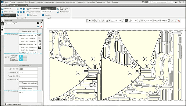
The application is designed to solve the problems of cutting materials: preliminary assessment of the need for materials; obtaining optimal cutting schemes and paperwork.
UNIT II
Four Exmples from Text Book will be given trainingOn software listed For the program Four problem will be given for self training with software to Trainee
The application allows you to lay out the contours of parts in FRW/DXF format, both in automatic and manual mode, taking into account the parameters of the equipment, edit the layout and assign business waste of material. Files of ready-made cutting and business waste maps are exported in DXF format and can then be used to prepare NC programs for CNC machines.
Cutting

UNIT III
Four Exmples from Text Book will be given trainingOn software listed For the program Four problem will be given for self training with software to Trainee
Main features of the application:
- Loading of contours of parts sorted by material and thickness in DXF/FRW format into the application;
- import of flat pattern patterns from the KOMPAS-3D 3D assembly with automatic sorting by material and thickness;
- cutting of linear (dimensional) materials;
- automatic creation and editing of the cutting chart in accordance with the selected parameters;
- assignment of business balances in manual and automatic mode;
- Output of cutting data: cutting charts (DXF), business balances (DXF/FRW), cutting sheets (DXF/FRW);
- calculation of the efficiency of cutting the material, the length of the cut;
- Generation of lists of cutting and business waste cards in the form of a completed document and a CSV file.
UNIT IV
Four Exmples from Text Book will be given trainingOn software listed For the program Four problem will be given for self training with software to Trainee
Requires for work: "KOMPAS-3D" or "KOMPAS-Graphic"System requirements correspond to the system requirements of KOMPAS-3D
KOMPAS 3D Application
Mechanical
UNIT I
Four Exmples from Text Book will be given trainingOn software listed For the program Four problem will be given for self training with software to Trainee
Four Exmples from Text Book will be given trainingOn software listed For the program Four problem will be given for self training with software to Trainee
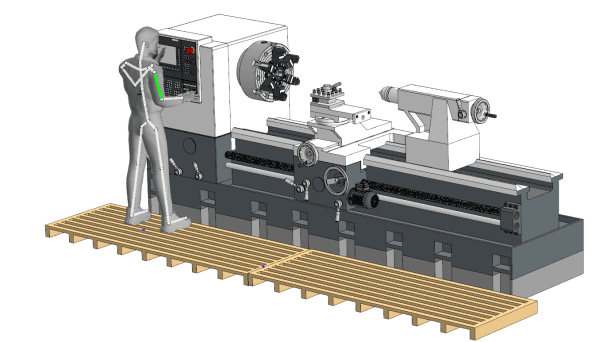
Ergonomics: Mannequins
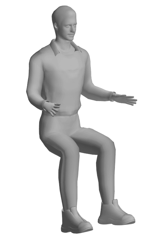
The application allows you to analyze the interaction of a person, taking into account his anthropometric parameters, with the designed products or workplaces to optimize and increase convenience and safety.
UNIT II
Four Exmples from Text Book will be given trainingOn software listed For the program Four problem will be given for self training with software to Trainee
Application functionality:
creation of a human figure (mannequin) taking into account the anthropometric characteristics in the model;positioning (changing position) in the model space;changing the position of the dummy's body parts by turning in the joints;Ability to select a preset mannequin pose from the built-in library of standard poses, as well as the ability to save a custom pose to the library.
creation of a human figure (mannequin) taking into account the anthropometric characteristics in the model;positioning (changing position) in the model space;changing the position of the dummy's body parts by turning in the joints;Ability to select a preset mannequin pose from the built-in library of standard poses, as well as the ability to save a custom pose to the library.
Ergonomics: Mannequins
UNIT III
Four Exmples from Text Book will be given trainingOn software listed For the program Four problem will be given for self training with software to Trainee
Manufacturer: ASCON-Design SystemsLLC Requires for work: KOMPAS-3DSystem requirements correspond to KOMPAS-3D system requiremen
UNIT IV
Four Exmples from Text Book will be given trainingOn software listed For the program Four problem will be given for self training with software to Trainee
KOMPAS 3D Application
Mechanical
UNIT I
Four Exmples from Text Book will be given trainingOn software listed For the program Four problem will be given for self training with software to Trainee
Four Exmples from Text Book will be given trainingOn software listed For the program Four problem will be given for self training with software to Trainee
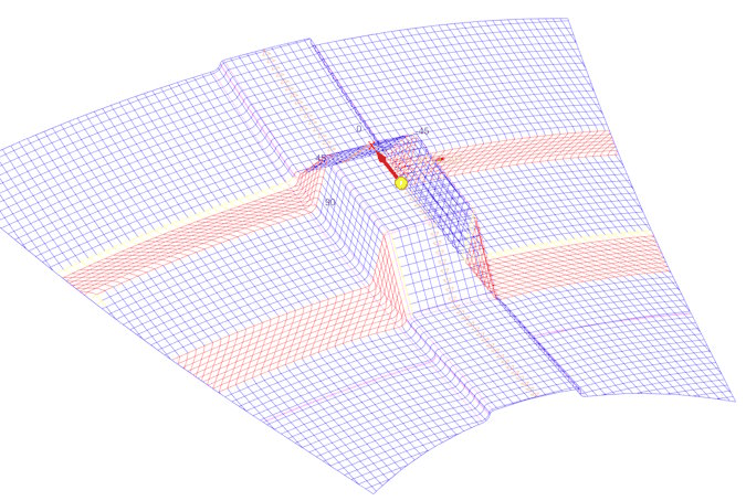
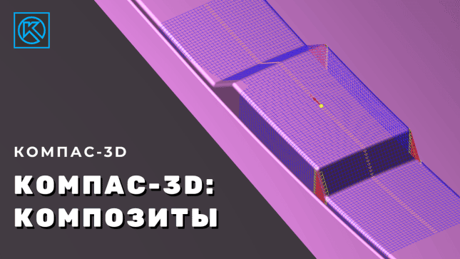
KOMPAS-Composites
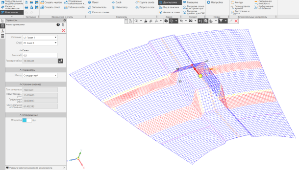
A computer program designed for the design and preparation of production of products from polymer composite materials.
UNIT II
Four Exmples from Text Book will be given trainingOn software listed For the program Four problem will be given for self training with software to Trainee
KOMPAS-Composites is an application for KOMPAS-3D version v24 or higher. The application is designed to automate the work on the design and technological preparation of the production of products made of laminated polymer composite materials (hereinafter referred to as PCM) with a fabric filler and manufactured by manual and/or automated layout.
KOMPAS-Composites

UNIT III
Four Exmples from Text Book will be given trainingOn software listed For the program Four problem will be given for self training with software to Trainee
The application allows you to:
create a three-dimensional appearance of a composite part and set requirements for the product at the design stage;analyze the laying for manufacturability;prepare cutting and data for production at the stage of technological preparation of production, including the use of high-tech equipment;to make changes at the stage of design and technological preparation of production.
App Online Help: https://help.ascon.ru/Composite3D/24/ru-RU/index.html
create a three-dimensional appearance of a composite part and set requirements for the product at the design stage;analyze the laying for manufacturability;prepare cutting and data for production at the stage of technological preparation of production, including the use of high-tech equipment;to make changes at the stage of design and technological preparation of production.
App Online Help: https://help.ascon.ru/Composite3D/24/ru-RU/index.html
UNIT IV
Four Exmples from Text Book will be given trainingOn software listed For the program Four problem will be given for self training with software to Trainee
Manufacturer: ASCON-Design SystemsLLC Requires for work: "KOMPAS-3D", "Materials and Assortments for KOMPAS"
KOMPAS 3D Application
Mechanical
UNIT I
Four Exmples from Text Book will be given trainingOn software listed For the program Four problem will be given for self training with software to Trainee
Four Exmples from Text Book will be given trainingOn software listed For the program Four problem will be given for self training with software to Trainee
Shafts and mechanical transmissions 3D. Gear cutting tools
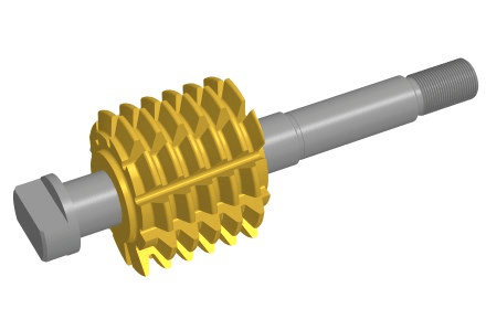
A specialized module for the basic application — Shafts and Mechanical Transmissions 3D. Designed for the design of gear cutting tools.
UNIT II
Four Exmples from Text Book will be given trainingOn software listed For the program Four problem will be given for self training with software to Trainee
Worm cutters and slotting cutters are the most common gear cutting tools, used for roughing and finishing gear cutting. The module will allow you to calculate and build models of worm cutters for cutting:
cylindrical gears with an involute profile (roughing and finishing cutters);Novikov cylindrical gears with two engagement lines;sprockets for driven roller and bushing chains;worm wheels of cylindrical worm gear (rough and finishing cutters);spline shafts with an involute profile;spline shafts with a straight-sided profile;
as well as gear chisels for cylindrical involute gearsworm wheels of cylindrical worm gear (rough and finishing cutters);spline shafts with an involute profile;spline shafts with a straight-sided profile;
as well as gear chisels for cylindrical involute gears
cylindrical gears with an involute profile (roughing and finishing cutters);Novikov cylindrical gears with two engagement lines;sprockets for driven roller and bushing chains;worm wheels of cylindrical worm gear (rough and finishing cutters);spline shafts with an involute profile;spline shafts with a straight-sided profile;
as well as gear chisels for cylindrical involute gearsworm wheels of cylindrical worm gear (rough and finishing cutters);spline shafts with an involute profile;spline shafts with a straight-sided profile;
as well as gear chisels for cylindrical involute gears
Shafts and mechanical transmissions 3D. Gear cutting tools
UNIT III
Four Exmples from Text Book will be given trainingOn software listed For the program Four problem will be given for self training with software to Trainee
The result of the work in the application is a fully designed drawing for a milling cutter or slotting (with callouts and a table of parameters) and its 3D model.
It is planned to develop design documentation for tools with the parameters of processed products (gears, worm wheels, spline shafts, sprockets) according to domestic and foreign standards. For involute gears and spline shafts, custom tool design (custom module, source contour or parameters) is available.
The gear or spline shaft data for the tool is obtained from the calculation modules or databases of the 3D Shaft and Mechanical Transmissions application.
It is planned to develop design documentation for tools with the parameters of processed products (gears, worm wheels, spline shafts, sprockets) according to domestic and foreign standards. For involute gears and spline shafts, custom tool design (custom module, source contour or parameters) is available.
The gear or spline shaft data for the tool is obtained from the calculation modules or databases of the 3D Shaft and Mechanical Transmissions application.
UNIT IV
Four Exmples from Text Book will be given trainingOn software listed For the program Four problem will be given for self training with software to Trainee
Features of the module:
It allows you to design any cutters or chisels - it is enough to get a drawing of the product or information according to which foreign standard to manufacture the tool.High speed of design. Typically, a qualified engineer spends two days calculating and documenting a standard hob or slot. The application allows you to reduce the development time to a few minutes.Manufacturer: ASCON-Design Systems
It allows you to design any cutters or chisels - it is enough to get a drawing of the product or information according to which foreign standard to manufacture the tool.High speed of design. Typically, a qualified engineer spends two days calculating and documenting a standard hob or slot. The application allows you to reduce the development time to a few minutes.Manufacturer: ASCON-Design Systems
The design of worm cutters for Novikov's spur gears requires a separately paid license for the Shafts and Mechanical Transmissions 3D Add-on Module.
The gear cutting part of the tool is a complete component of the 2D model of the application. This implementation allows you to create not only standard milling cutters for a cylindrical mandrel, but also to combine the gear cutting part of the tool with special shanks designed for specific gear cutting machines.
The gear cutting part of the tool is a complete component of the 2D model of the application. This implementation allows you to create not only standard milling cutters for a cylindrical mandrel, but also to combine the gear cutting part of the tool with special shanks designed for specific gear cutting machines.
KOMPAS 3D Application
Mechanical
UNIT I
Four Exmples from Text Book will be given trainingOn software listed For the program Four problem will be given for self training with software to Trainee
Four Exmples from Text Book will be given trainingOn software listed For the program Four problem will be given for self training with software to Trainee
Mechanics: Springs
Mechanics: Springs
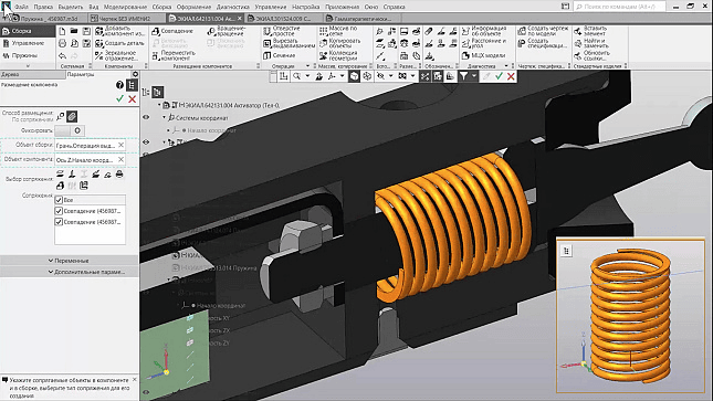
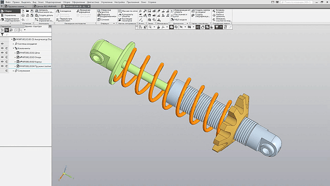
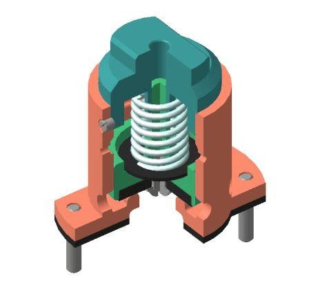
The application allows you to perform design and verification calculations of compression, tension, torsion, as well as disc, conical and shaped springs. Based on the results of the calculations, drawings and 3D models are automatically generated.
UNIT II
Four Exmples from Text Book will be given trainingOn software listed For the program Four problem will be given for self training with software to Trainee
The appendix is based on the following calculation methods:
compression and tension springs – GOST 13764-86, GOST 13765-86;disc springs – GOST 3057-90;torsional springs – a method from the book by V.I. Anuryev "Handbook of a Mechanical Engineer Designer", Volume 3;conical and shaped springs are a technique from the book by S. D. Ponomarev, L. E. Andreev "Calculation of elastic elements of machines and devices".
compression and tension springs – GOST 13764-86, GOST 13765-86;disc springs – GOST 3057-90;torsional springs – a method from the book by V.I. Anuryev "Handbook of a Mechanical Engineer Designer", Volume 3;conical and shaped springs are a technique from the book by S. D. Ponomarev, L. E. Andreev "Calculation of elastic elements of machines and devices".
Mechanics: Springs
Mechanics: Springs
UNIT III
Four Exmples from Text Book will be given trainingOn software listed For the program Four problem will be given for self training with software to Trainee
As a result of the design calculation, the application offers a variety of solutions that meet the initial data, from which the designer can choose the optimal one according to one or more criteria.
When creating a spring drawing, you can select the type of hooks, automatically set dimensions, extension views, warp diagrams, or force diagrams.
After you insert a spring model into an assembly, you can change the length of the spring, allowing you to set the part to a working or intermediate state
When creating a spring drawing, you can select the type of hooks, automatically set dimensions, extension views, warp diagrams, or force diagrams.
After you insert a spring model into an assembly, you can change the length of the spring, allowing you to set the part to a working or intermediate state
UNIT IV
Four Exmples from Text Book will be given trainingOn software listed For the program Four problem will be given for self training with software to Trainee
As practice shows, the use of the Springs application allows you to increase the speed of design and release of design documentation of springs by 15-20 times.
Manufacturer: ASCON-Design SystemsLLC Requires for work: KOMPAS-3DSystem requirements correspond to KOMPAS-3D system requirements
Manufacturer: ASCON-Design SystemsLLC Requires for work: KOMPAS-3DSystem requirements correspond to KOMPAS-3D system requirements
KOMPAS 3D Application
Mechanical
UNIT I
Four Exmples from Text Book will be given trainingOn software listed For the program Four problem will be given for self training with software to Trainee
Four Exmples from Text Book will be given trainingOn software listed For the program Four problem will be given for self training with software to Trainee
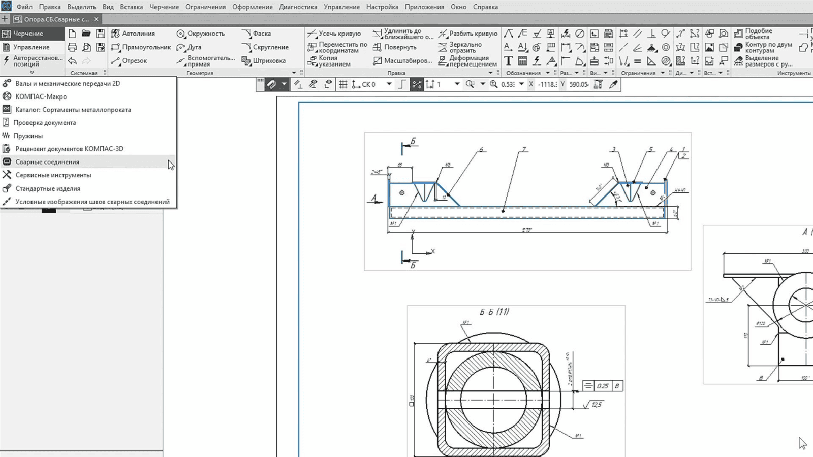
Catalog: Welds
Catalog: Welds
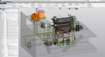
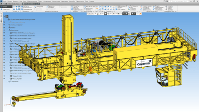
A set of applications for the quick design of an electronic model of a product containing welded joints.
If the model or drawing is saturated with various welds and other permanent joints, it is quite difficult not to make a mistake when designing or editing their designations. Catalog: Welds will help to simplify the designation in the model and avoid errors when specifying the numbers and number of seams in the drawing. The catalogue consists of:
UNIT II
Four Exmples from Text Book will be given trainingOn software listed For the program Four problem will be given for self training with software to Trainee
nseparable connections
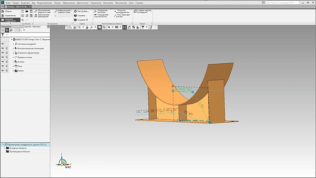
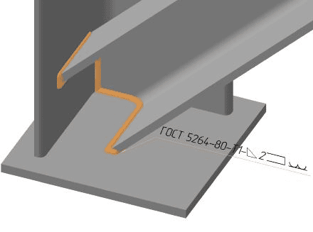
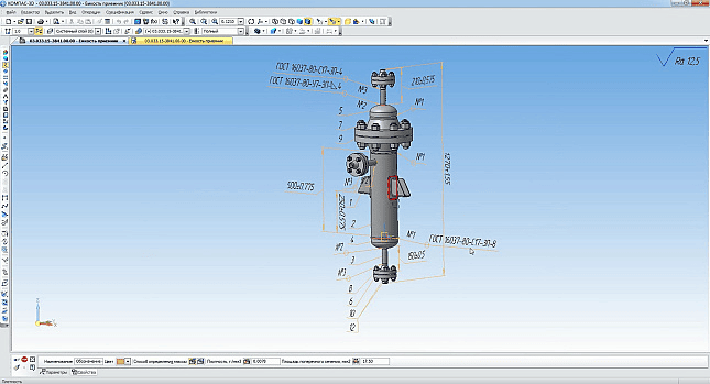
Designation of the seam and indication of its symbol directly in the model. The created symbol is automatically transferred to the weldment drawing. In addition, the length of the weld can also be transferred to the drawing. The following ways to create a symbol in the model are available: by faces (in this case, the faces of the first and second objects are alternately specified to build a welding seam between them); along the ribs (the seam is built according to the ribs specified in the model); by points (a symbol of resistance welding is created);The ability to create an adhesive connection between the elements to be connected in the model and specify a symbol for it. The following ways to create a symbol in a model are available: between faces; between bodies; and along the sketch contour that bounds the gluing area.Quick marking of welds according to GOST is possible due to the dialog box, in which you can select welding parameters (standard, type, method, etc.). When you enter a new seam designation in the current document, the next sequence number is automatically placed. You can insert a symbol from a custom template (a set of commonly used seams).
Designation of the seam and indication of its symbol directly in the model. The created symbol is automatically transferred to the weldment drawing. In addition, the length of the weld can also be transferred to the drawing. The following ways to create a symbol in the model are available: by faces (in this case, the faces of the first and second objects are alternately specified to build a welding seam between them); along the ribs (the seam is built according to the ribs specified in the model); by points (a symbol of resistance welding is created);The ability to create an adhesive connection between the elements to be connected in the model and specify a symbol for it. The following ways to create a symbol in a model are available: between faces; between bodies; and along the sketch contour that bounds the gluing area.Quick marking of welds according to GOST is possible due to the dialog box, in which you can select welding parameters (standard, type, method, etc.). When you enter a new seam designation in the current document, the next sequence number is automatically placed. You can insert a symbol from a custom template (a set of commonly used seams).
Catalog: Welds
Catalog: Welds
UNIT III
Four Exmples from Text Book will be given trainingOn software listed For the program Four problem will be given for self training with software to Trainee
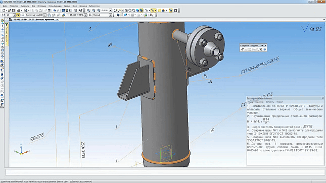
Ability to create weld symbols on drawings in accordance with GOST 2.312-72, ISO 2553:1992 (DIN 22553-1997) standards, create tables of welds.Checking the designations of welds in the current document according to GOST before automatically building a table of welds in accordance with the selected style. Validation avoids inconsistencies in the types of symbols in the drawing, the number of seams, and their numbers. The style of the weld table can be selected from the list or created by yourself.Insert weld structural elements into a drawing or sketch model. In the dialog box, by selecting the parameters of the desired connection, you can insert an image of the weld, or the groove of its edges. Images of structural elements of joints are available according to GOST 5264-80, GOST 8713-79, GOST 14771-76, GOST 14806-80.
Symbols for permanent connections
Symbols for permanent connections
UNIT IV
Four Exmples from Text Book will be given trainingOn software listed For the program Four problem will be given for self training with software to Trainee
Symbols for permanent connections
Indication of the image of weld legs on the drawing and designation of the seams in accordance with GOST 21.502-2007.Ability to adjust the leg type (equilateral or non-equilateral) and the direction of the rounding (inward or outward). Leg drawing is also available without rounding — in the form of a triangle.Selection of the seam type when inserting its image into the document according to GOST 21.502-2007: factory or installation, solid or discontinuous - and indicate whether the seam line should be visible or invisible. The geometric parameters of the seam images (stroke length, distance between strokes and stroke groups, line type, etc.) are user-configurable.
Indication of the image of weld legs on the drawing and designation of the seams in accordance with GOST 21.502-2007.Ability to adjust the leg type (equilateral or non-equilateral) and the direction of the rounding (inward or outward). Leg drawing is also available without rounding — in the form of a triangle.Selection of the seam type when inserting its image into the document according to GOST 21.502-2007: factory or installation, solid or discontinuous - and indicate whether the seam line should be visible or invisible. The geometric parameters of the seam images (stroke length, distance between strokes and stroke groups, line type, etc.) are user-configurable.
KOMPAS 3D Application
Mechanical
UNIT I
Four Exmples from Text Book will be given trainingOn software listed For the program Four problem will be given for self training with software to Trainee
Four Exmples from Text Book will be given trainingOn software listed For the program Four problem will be given for self training with software to Trainee
3D Stamps
3D Stamps
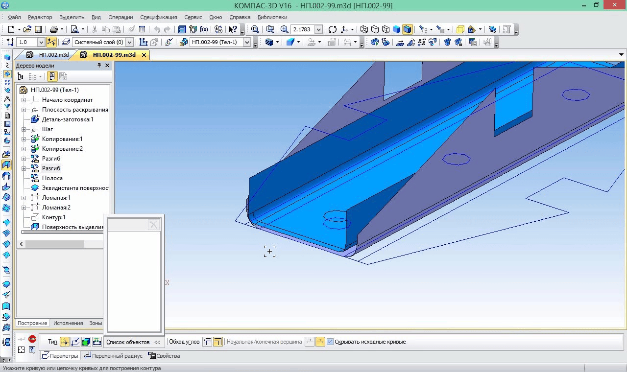
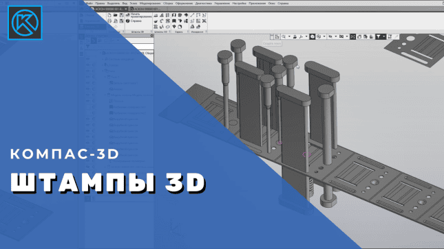
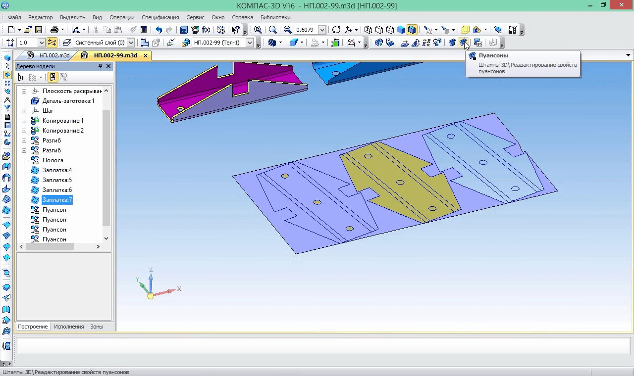
The Dies 3D application is designed to automate design and technological work when designing dies for sheet material products. It allows you to generate a set of technical documentation necessary for the production of a die.
UNIT II
Four Exmples from Text Book will be given trainingOn software listed For the program Four problem will be given for self training with software to Trainee
The application provides:
Unfold the source part into a workpiece (flat pattern) and create part-to-blank transformation steps.Strip design. To ensure high productivity and save material, the application will automatically form the optimal cutting and working area of the die.Design of punches. Specifies the step placement and configuration of separating and massing punches.Design of the die package. The pressure center of the die is determined automatically. Depending on the grade and thickness of the material, a gap is formed between the punch and the die. The configuration and position of the punches are specified. The press is selected based on its characteristics and die dimensions from the list of the most used equipment at enterprises.Automatic generation of a set of documentation required for the production of a stamp (3D models, assembly drawings, specifications, detailing) in accordance with the Unified System of Structural Documentation.
Unfold the source part into a workpiece (flat pattern) and create part-to-blank transformation steps.Strip design. To ensure high productivity and save material, the application will automatically form the optimal cutting and working area of the die.Design of punches. Specifies the step placement and configuration of separating and massing punches.Design of the die package. The pressure center of the die is determined automatically. Depending on the grade and thickness of the material, a gap is formed between the punch and the die. The configuration and position of the punches are specified. The press is selected based on its characteristics and die dimensions from the list of the most used equipment at enterprises.Automatic generation of a set of documentation required for the production of a stamp (3D models, assembly drawings, specifications, detailing) in accordance with the Unified System of Structural Documentation.
3D Stamps
3D Stamps
UNIT III
Four Exmples from Text Book will be given trainingOn software listed For the program Four problem will be given for self training with software to Trainee
The appendix contains:
A database of press equipment, which includes more than 20 models of presses.Knowledge base of die designs with the possibility of expanding it taking into account additional user requirements.Parametric libraries of 3D GOST parts and structural elements of dies.
A database of press equipment, which includes more than 20 models of presses.Knowledge base of die designs with the possibility of expanding it taking into account additional user requirements.Parametric libraries of 3D GOST parts and structural elements of dies.
UNIT IV
Four Exmples from Text Book will be given trainingOn software listed For the program Four problem will be given for self training with software to Trainee
The application allows you to:
Design separating dies: with a rigid puller, with a top clamp, combined action dies.To design dies of sequential action with a combination of both separating and form-generating operations. In combination with both upper and lower pressure.Design bending dies.
Design separating dies: with a rigid puller, with a top clamp, combined action dies.To design dies of sequential action with a combination of both separating and form-generating operations. In combination with both upper and lower pressure.Design bending dies.
KOMPAS 3D Application
Mechanical
UNIT I
Four Exmples from Text Book will be given trainingOn software listed For the program Four problem will be given for self training with software to Trainee
Four Exmples from Text Book will be given trainingOn software listed For the program Four problem will be given for self training with software to Trainee
3D Molds
3D Molds
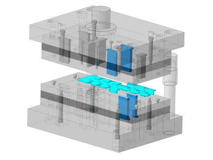
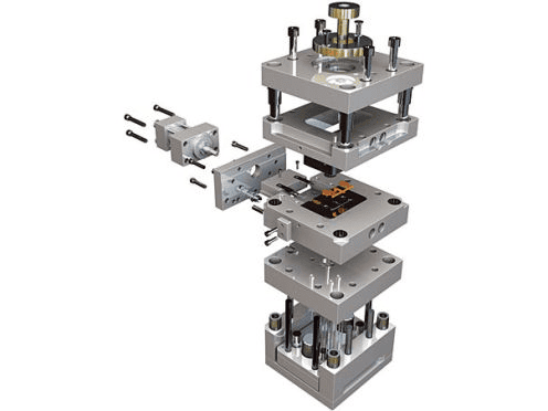
The Mold 3D application is designed to automate the design and technological work of designing molds for plastic injection molding, and the formation of a set of technical documentation necessary for the production of a mold.
UNIT II
Four Exmples from Text Book will be given trainingOn software listed For the program Four problem will be given for self training with software to Trainee
The application provides:
Analysis of the 3D model of the part and design of the mold forming elements.Automatic or interactive mold package design.Control of the design admissibility of mold parts as a necessary condition for mold performance.Automatic generation of a set of documentation necessary for the release of a mold (3D models, assembly drawings, specifications, detailing) in accordance with the Unified System of Production Systems.
Analysis of the 3D model of the part and design of the mold forming elements.Automatic or interactive mold package design.Control of the design admissibility of mold parts as a necessary condition for mold performance.Automatic generation of a set of documentation necessary for the release of a mold (3D models, assembly drawings, specifications, detailing) in accordance with the Unified System of Production Systems.
3D Molds
3D Molds
UNIT III
Four Exmples from Text Book will be given trainingOn software listed For the program Four problem will be given for self training with software to Trainee
3D Molds contains:
A database of equipment that includes more than 60 models of injection molding machines.Knowledge base of mold designs with the possibility of expanding it taking into account additional user requirements;Parametric libraries of mold structural element drawings.
A database of equipment that includes more than 60 models of injection molding machines.Knowledge base of mold designs with the possibility of expanding it taking into account additional user requirements;Parametric libraries of mold structural element drawings.
UNIT IV
Four Exmples from Text Book will be given trainingOn software listed For the program Four problem will be given for self training with software to Trainee
The application allows you to:
Design molds of "pusher removal", "plate removal" structures and their combinations.Design molds with one or two parallel opening planes.Design molds with a side connector (sliders).Design molds with a "typical" or "column-mounting" method of centering the moving and stationary parts.Modify the designs and design features of mold elements in order to fully adapt the manufacturing technology and toolmaking capabilities.
Design molds of "pusher removal", "plate removal" structures and their combinations.Design molds with one or two parallel opening planes.Design molds with a side connector (sliders).Design molds with a "typical" or "column-mounting" method of centering the moving and stationary parts.Modify the designs and design features of mold elements in order to fully adapt the manufacturing technology and toolmaking capabilities.
KOMPAS 3D Application
Mechanical
UNIT I
Four Exmples from Text Book will be given trainingOn software listed For the program Four problem will be given for self training with software to Trainee
Four Exmples from Text Book will be given trainingOn software listed For the program Four problem will be given for self training with software to Trainee
3D express molds
3D express molds
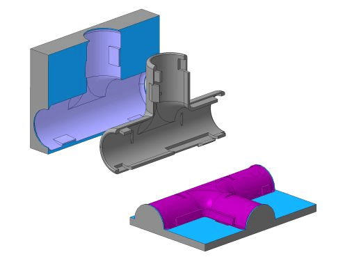
The 3D Express Molds application is designed to automate the analysis of the 3D model of the part and the design of forming molds, including side sliders.
UNIT II
Four Exmples from Text Book will be given trainingOn software listed For the program Four problem will be given for self training with software to Trainee
Main functions:
analysis of disclosure, the presence of zero or negative slopes.Assigning the surfaces of the 3D model to the movable or stationary parts of the mold, to the side sliders;construction of the opening line and surface, patches of internal holes;production of blanks forming molds;gating system modeling
analysis of disclosure, the presence of zero or negative slopes.Assigning the surfaces of the 3D model to the movable or stationary parts of the mold, to the side sliders;construction of the opening line and surface, patches of internal holes;production of blanks forming molds;gating system modeling
3D express molds
3D express molds
UNIT III
Four Exmples from Text Book will be given trainingOn software listed For the program Four problem will be given for self training with software to Trainee
3D Molds contains:
A database of equipment that includes more than 60 models of injection molding machines.Knowledge base of mold designs with the possibility of expanding it taking into account additional user requirements;Parametric libraries of mold structural element drawings.
A database of equipment that includes more than 60 models of injection molding machines.Knowledge base of mold designs with the possibility of expanding it taking into account additional user requirements;Parametric libraries of mold structural element drawings.
UNIT IV
Four Exmples from Text Book will be given trainingOn software listed For the program Four problem will be given for self training with software to Trainee
The application allows you to:
Design molds of "pusher removal", "plate removal" structures and their combinations.Design molds with one or two parallel opening planes.Design molds with a side connector (sliders).Design molds with a "typical" or "column-mounting" method of centering the moving and stationary parts.Modify the designs and design features of mold elements in order to fully adapt the manufacturing technology and toolmaking capabilities.
Design molds of "pusher removal", "plate removal" structures and their combinations.Design molds with one or two parallel opening planes.Design molds with a side connector (sliders).Design molds with a "typical" or "column-mounting" method of centering the moving and stationary parts.Modify the designs and design features of mold elements in order to fully adapt the manufacturing technology and toolmaking capabilities.
KOMPAS 3D Application
Mechanical
UNIT I
Four Exmples from Text Book will be given trainingOn software listed For the program Four problem will be given for self training with software to Trainee
Four Exmples from Text Book will be given trainingOn software listed For the program Four problem will be given for self training with software to Trainee
Coupling Catalog
Coupling Catalog
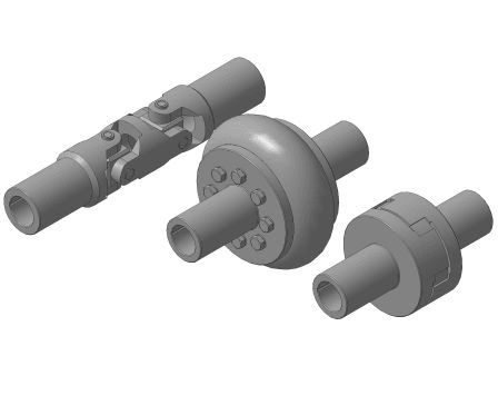
The application is designed to create three-dimensional models and drawings of standard machine-building couplings of various types.
UNIT II
Four Exmples from Text Book will be given trainingOn software listed For the program Four problem will be given for self training with software to Trainee
The application allows you to create three-dimensional models and two-dimensional images of the following couplings:
Blind couplings:flanged according to GOST 20761-96;Rigid compensating:toothed according to GOST R 50895-96;hinged according to GOST 5147-97;articulated with a bushing according to GOST 5147-97;toothed according to GOST R 50895-96;toothed MZP as per GOST R 50895-96;Elastic compensating:elastic bushing-pin according to GOST 21424-93;a coupling with a sprocket as per GOST R 50894-96;with a torus-shaped shell according to GOST R 50892-96.
Blind couplings:flanged according to GOST 20761-96;Rigid compensating:toothed according to GOST R 50895-96;hinged according to GOST 5147-97;articulated with a bushing according to GOST 5147-97;toothed according to GOST R 50895-96;toothed MZP as per GOST R 50895-96;Elastic compensating:elastic bushing-pin according to GOST 21424-93;a coupling with a sprocket as per GOST R 50894-96;with a torus-shaped shell according to GOST R 50892-96.
Coupling Catalog
Coupling Catalog
UNIT III
Four Exmples from Text Book will be given trainingOn software listed For the program Four problem will be given for self training with software to Trainee
When creating a coupling, it is possible to automatically generate a cutout in the model (assembly) or a section in the drawing. The coupling model is inserted into the active document as a parameterized three-dimensional macro object or a two-dimensional image, which makes it easy to edit the resulting coupling using the library. When editing in the library, you can not only change the size of a given coupling, but also replace it with a new coupling of a different type. You can automatically create a BOM object for standardized couplings. The main dimensions for each standard size of couplings can be automatically entered on the created drawing.
UNIT IV
Four Exmples from Text Book will be given trainingOn software listed For the program Four problem will be given for self training with software to Trainee
The library also contains the values of the rated torque, rotational speed and all geometric dimensions (according to GOST) for each type of formed couplings.
Catalog: Couplings will significantly reduce the time for the design of machine-building drives (gearboxes), as well as any other industrial units in which the connection of shafts and the transmission of rotary motion between them are used.
Manufacturer: ASCON-Design SystemsLLC Requires for work: KOMPAS-3DSystem requirements correspond to KOMPAS-3D system requirements
Catalog: Couplings will significantly reduce the time for the design of machine-building drives (gearboxes), as well as any other industrial units in which the connection of shafts and the transmission of rotary motion between them are used.
Manufacturer: ASCON-Design SystemsLLC Requires for work: KOMPAS-3DSystem requirements correspond to KOMPAS-3D system requirements
KOMPAS 3D Application
Mechanical
UNIT I
Four Exmples from Text Book will be given trainingOn software listed For the program Four problem will be given for self training with software to Trainee
Four Exmples from Text Book will be given trainingOn software listed For the program Four problem will be given for self training with software to Trainee
Detachable connections
Detachable connections
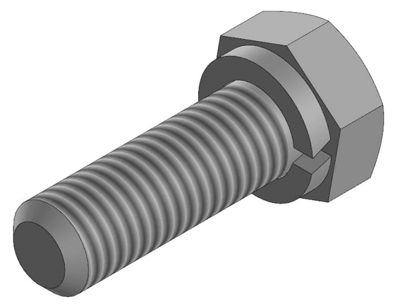
An application for KOMPAS-3D, which allows you to form and place a set of fasteners in an assembly.
UNIT II
Four Exmples from Text Book will be given trainingOn software listed For the program Four problem will be given for self training with software to Trainee
A separately paid license is required to use the Connectors app.
Main features of the application:
creation of detachable bolt and screw connections;control of the composition of sets of fasteners in the connection;positioning (placement) of fasteners in the assembly unit;selection of the length of bolts and screws for the thickness and composition of the connection;selection of counterparts (washers, nuts) for a bolt or screw.
Main features of the application:
creation of detachable bolt and screw connections;control of the composition of sets of fasteners in the connection;positioning (placement) of fasteners in the assembly unit;selection of the length of bolts and screws for the thickness and composition of the connection;selection of counterparts (washers, nuts) for a bolt or screw.
Detachable connections
Detachable connections
UNIT III
Four Exmples from Text Book will be given trainingOn software listed For the program Four problem will be given for self training with software to Trainee
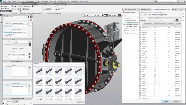
The Detachable Connections app includes three commands that add different sets of elements.
Bolted connection is a set of bolts, washers and nuts;Screw connection – a set of screw, washers and nuts;Washers/nuts for connection are a set of washers and nuts
Bolted connection is a set of bolts, washers and nuts;Screw connection – a set of screw, washers and nuts;Washers/nuts for connection are a set of washers and nuts
UNIT IV
Four Exmples from Text Book will be given trainingOn software listed For the program Four problem will be given for self training with software to Trainee
T
he set of elements is formed on the basis of the nomenclature of the application "Standard Products for COMPASS" (requires a separately paid license).
Manufacturer: ASCON-Design SystemsLLC Requires for work: "KOMPAS-3D", "Standard Products: Fasteners for KOMPAS-3D"System requirements correspond to the system requirements of KOMPAS-3DLLC Requires for work: "KOMPAS-3D", "Standard Products: Fasteners for KOMPAS-3D"System requirements correspond to the system requirements of KOMPAS-3D
Manufacturer: ASCON-Design SystemsLLC Requires for work: "KOMPAS-3D", "Standard Products: Fasteners for KOMPAS-3D"System requirements correspond to the system requirements of KOMPAS-3DLLC Requires for work: "KOMPAS-3D", "Standard Products: Fasteners for KOMPAS-3D"System requirements correspond to the system requirements of KOMPAS-3D
KOMPAS 3D Application
Mechanical
UNIT I
Four Exmples from Text Book will be given trainingOn software listed For the program Four problem will be given for self training with software to Trainee
Four Exmples from Text Book will be given trainingOn software listed For the program Four problem will be given for self training with software to Trainee
Standard Products: Faeers for KOMPAS
Standard Products: Faeers for KOMPAS
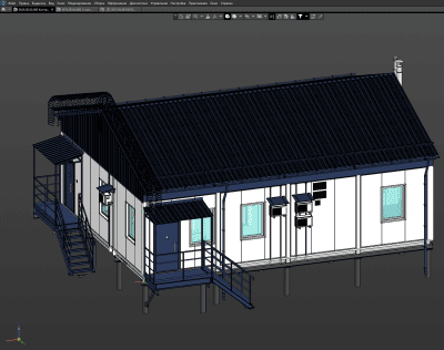
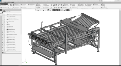
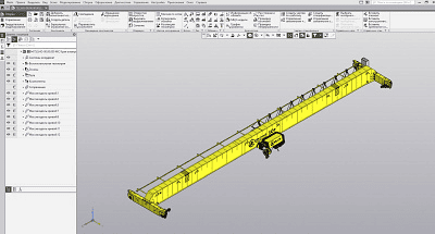
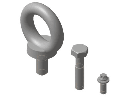
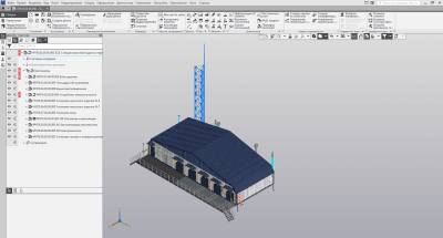
The catalog "Standard Products: Fasteners" contains fasteners according to the standards of GOST, ISO, DIN, OST 92: bolts, screws, nuts, washers, studs, cotter pins, rivets, etc.
UNIT II
Four Exmples from Text Book will be given trainingOn software listed For the program Four problem will be given for self training with software to Trainee
Standard Products: Fasteners for KOMPAS include:
fasteners according to GOST - more than 238,531 models;fasteners according to DIN, ISO – according to DIN 50 851 models, according to ISO 21 520 models;products according to OST 92 – 8627 models;openings of various types;Fastening connection packages.
fasteners according to GOST - more than 238,531 models;fasteners according to DIN, ISO – according to DIN 50 851 models, according to ISO 21 520 models;products according to OST 92 – 8627 models;openings of various types;Fastening connection packages.
Standard Products: Fasteners for KOMPAS
Standard Products: Fasteners for KOMPAS
UNIT III
Four Exmples from Text Book will be given trainingOn software listed For the program Four problem will be given for self training with software to Trainee
The catalog "Standard Products: Fasteners" contains fasteners according to the standards of GOST, ISO, DIN, OST 92: bolts, screws, nuts, washers, studs, cotter pins, rivets, etc
UNIT IV
Four Exmples from Text Book will be given trainingOn software listed For the program Four problem will be given for self training with software to Trainee
Manufacturer: ASCON-Business Solutions
LLC Requires for work: "KOMPAS-3D" or "KOMPAS-Graphic"
System requirements correspond to the system requirements of KOMPAS-3D
LLC Requires for work: "KOMPAS-3D" or "KOMPAS-Graphic"
System requirements correspond to the system requirements of KOMPAS-3D
KOMPAS 3D Application
Mechanical
UNIT I
Four Exmples from Text Book will be given trainingOn software listed For the program Four problem will be given for self training with software to Trainee
Four Exmples from Text Book will be given trainingOn software listed For the program Four problem will be given for self training with software to Trainee
Standard Products: Parts, assemblies and structural elements for COMPASS
Standard Products: Parts, assemblies and structural elements for COMPASS
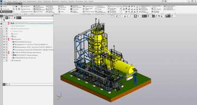
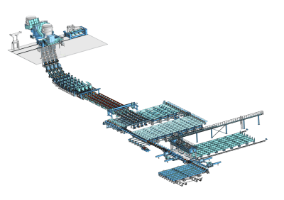
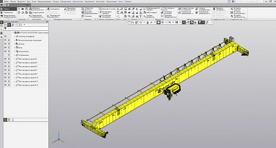
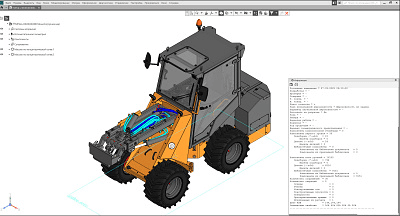
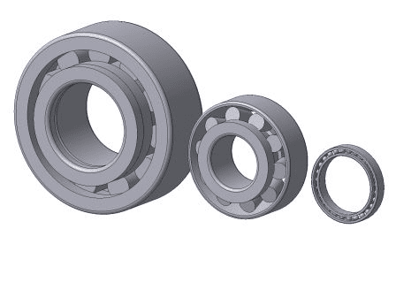
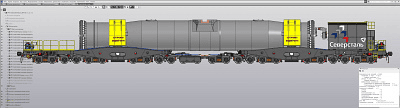
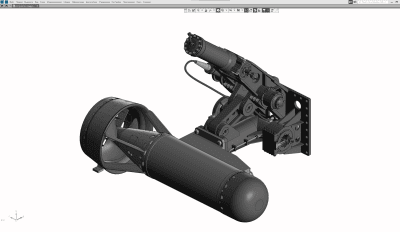
The catalog "Standard Products: Parts, Assemblies and Structural Elements" contains an extensive list of elements.
UNIT II
Four Exmples from Text Book will be given trainingOn software listed For the program Four problem will be given for self training with software to Trainee
Bearings and machine parts (ball and roller bearings, cuffs and keys, axles, etc.) – 403,238 elements;Pipeline parts and fittings (flanges, elbows, tees, plugs, etc., as well as pipe fastening parts) – 191,887 models;Parts of pneumatic and hydraulic systems (union nuts, fittings, nipples, crosses, tees, etc.) – 6603 models;Machine tool elements — 13,812 models;Parts and assemblies of vessels and apparatus (flanges, bottoms, slinging devices, supports, paws, etc.) — 143,081 models.
Standard Products: Parts, assemblies and structurelements for COMPASS
Standard Products: Parts, assemblies and structurelements for COMPASS
UNIT III
Four Exmples from Text Book will be given trainingOn software listed For the program Four problem will be given for self training with software to Trainee
The catalog "Standard Products: Fasteners" contains fasteners according to the standards of GOST, ISO, DIN, OST 92: bolts, screws, nuts, washers, studs, cotter pins, rivets, etc
UNIT IV
Four Exmples from Text Book will be given trainingOn software listed For the program Four problem will be given for self training with software to Trainee
KOMPAS 3D Application
Mechanical
UNIT I
Four Exmples from Text Book will be given trainingOn software listed For the program Four problem will be given for self training with software to Trainee
Four Exmples from Text Book will be given trainingOn software listed For the program Four problem will be given for self training with software to Trainee
Standard Products: 3D Electrical Apparatus and Fittings f COMPASS
Standard Products: 3D Electrical Apparatus and Fittings f COMPASS
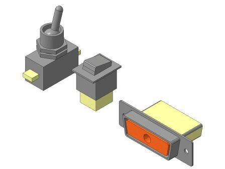
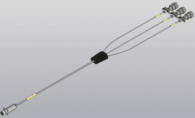
Standard products: 3D electrical apparatus and fittings for KOMPAS contains 33,783 products often used in the sign of electronic equipment.
UNIT II
Four Exmples from Text Book will be given trainingOn software listed For the program Four problem will be given for self training with software to Trainee
Among them:
Terminals and clamps;Covers for cylindrical connectors;Petals;Cable lugs and sleeves;Load-bearing panels, type U;Toggle switches;Connecting boards;Rectangular electric connectors;Cylindrical electric connectors;Installation elements.
Terminals and clamps;Covers for cylindrical connectors;Petals;Cable lugs and sleeves;Load-bearing panels, type U;Toggle switches;Connecting boards;Rectangular electric connectors;Cylindrical electric connectors;Installation elements.
Standard Products: 3D Electrical Apparatus and Fittings for COMPASS
Standard Products: 3D Electrical Apparatus and Fittings for COMPASS
UNIT III
Four Exmples from Text Book will be given trainingOn software listed For the program Four problem will be given for self training with software to Trainee
When you insert a standard product into a drawing or assembly model, you enter the information necessary for the subsequent generation of a bill of materials.
Thus, the extensive composition of the COMPASS Standard Products catalog allows the engineer to increase work productivity through the use of standard structural elements.
Thus, the extensive composition of the COMPASS Standard Products catalog allows the engineer to increase work productivity through the use of standard structural elements.
UNIT IV
Four Exmples from Text Book will be given trainingOn software listed For the program Four problem will be given for self training with software to Trainee
KOMPAS 3D Application
Mechanical
UNIT I
Four Exmples from Text Book will be given trainingOn software listed For the program Four problem will be given for self training with software to Trainee
Four Exmples from Text Book will be given trainingOn software listed For the program Four problem will be given for self training with software to Trainee
Materials and Assortnts for KOMPAS
Materials and Assortnts for KOMPAS
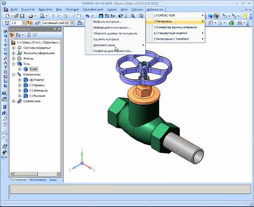
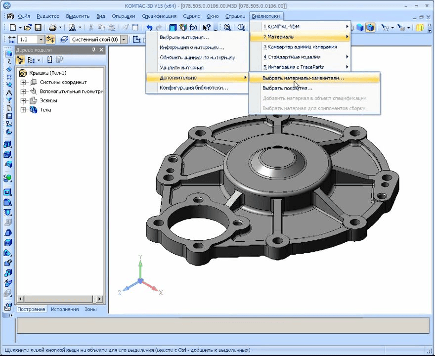
The library contains an extensive list of materials and assortments, information on the properties of materials, purpose and scope of application, substitutes and replacement conditions, information on regulatory documents, etc.
UNIT II
Four Exmples from Text Book will be given trainingOn software listed For the program Four problem will be given for self training with software to Trainee
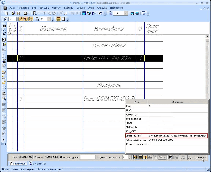
This application is very convenient to use together with other modules KOMPAS-3D and KOMPAS-Graph. It provides the constructor:
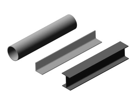
Designations and documents for the supply of ferrous and non-ferrous metals, their alloys and non-metallic materials (including construction materials);Physical, mechanical, technological properties of structural materials, their purpose and areas of application;Types of assortment (shaped, sheet, profile, etc.) made from these materials, including lists of standard sizes produced by industry;Lubricant grades with data on their properties and applications;Grades of paint, metal and non-metallic coatings, including characteristics and operating conditions of coatings;Tables of correspondence between Russian and foreign steel grades.
Designations and documents for the supply of ferrous and non-ferrous metals, their alloys and non-metallic materials (including construction materials);Physical, mechanical, technological properties of structural materials, their purpose and areas of application;Types of assortment (shaped, sheet, profile, etc.) made from these materials, including lists of standard sizes produced by industry;Lubricant grades with data on their properties and applications;Grades of paint, metal and non-metallic coatings, including characteristics and operating conditions of coatings;Tables of correspondence between Russian and foreign steel grades.
Materials and Assorte for KOMPAS
Materials and Assorte for KOMPAS
UNIT III
Four Exmples from Text Book will be given trainingOn software listed For the program Four problem will be given for self training with software to Trainee
The total number of materials in the library is 18,645 titles. Including:
2402 domestic grades of steels and alloys;2291 foreign grades of steels and alloys;147 marks of pig iron;1638 grades of non-ferrous metals and alloys;304 types of alloying alloys;706 grades of oils and lubricants;363 brands of varnishes and paints;941 brands of plastics;523 brands of adhesives;1221 names of welding consumables; + 266 soldering materials;665 types of wires and cables;1559 items of building materials;132 types of galvanic coatings + 951 copies of coatings;389 items of components for composite materials.
2402 domestic grades of steels and alloys;2291 foreign grades of steels and alloys;147 marks of pig iron;1638 grades of non-ferrous metals and alloys;304 types of alloying alloys;706 grades of oils and lubricants;363 brands of varnishes and paints;941 brands of plastics;523 brands of adhesives;1221 names of welding consumables; + 266 soldering materials;665 types of wires and cables;1559 items of building materials;132 types of galvanic coatings + 951 copies of coatings;389 items of components for composite materials.
UNIT IV
Four Exmples from Text Book will be given trainingOn software listed For the program Four problem will be given for self training with software to Trainee
The database contains 47,555 assortments.
In addition to basic information about materials and assortments, the directory contains information about manufacturers and suppliers, data on friction coefficients, gluing conditions of various materials.
The database of materials is constantly updated and kept up to date. The information contained in it is checked for compliance with the current regulatory documentation (GOST, OST, TU, etc.).
Manufacturer: ASCON-Business SolutionsLLC Requires for work: "KOMPAS-3D" or "KOMPAS-Graphic"System requirements correspond to the system requirements of KOMPAS-3D
In addition to basic information about materials and assortments, the directory contains information about manufacturers and suppliers, data on friction coefficients, gluing conditions of various materials.
The database of materials is constantly updated and kept up to date. The information contained in it is checked for compliance with the current regulatory documentation (GOST, OST, TU, etc.).
Manufacturer: ASCON-Business SolutionsLLC Requires for work: "KOMPAS-3D" or "KOMPAS-Graphic"System requirements correspond to the system requirements of KOMPAS-3D
KOMPAS 3D Application
Mechanical
UNIT I
Four Exmples from Text Book will be given trainingOn software listed For the program Four problem will be given for self training with software to Trainee
Four Exmples from Text Book will be given trainingOn software listed For the program Four problem will be given for self training with software to Trainee
ESKD Classifier
ESKD Classifier
A large number of design and technological tasks require the classification of parts and assembly units according to their geometric characteristics.
UNIT II
Four Exmples from Text Book will be given trainingOn software listed For the program Four problem will be given for self training with software to Trainee
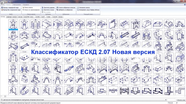
The ESKD classifier is an application for quick and unambiguous assignment of the code of the designed part.
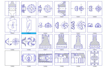
The classifier contains a unique database of vector images — about 8000 sketches of machine-building parts (classes 71 to 75), as well as textual descriptions of technological characteristics of parts and assembly units (classes 04 to 94).
The classifier contains a unique database of vector images — about 8000 sketches of machine-building parts (classes 71 to 75), as well as textual descriptions of technological characteristics of parts and assembly units (classes 04 to 94).
ESKD Classifier
ESKD Classifier
UNIT III
Four Exmples from Text Book will be given trainingOn software listed For the program Four problem will be given for self training with software to Trainee
To assign code, the designer simply answers five questions about the geometry of the part and reviews the suggested sketches. There is also a fuzzy search mode for a sketch by geometric features.
The assigned code is used for justified borrowing of standard design and technological design solutions.
The assigned code is used for justified borrowing of standard design and technological design solutions.
UNIT IV
Four Exmples from Text Book will be given trainingOn software listed For the program Four problem will be given for self training with software to Trainee
ESKD Classifier
ESKD Classifier
KOMPAS 3D Application
Mechanical
UNIT I
Four Exmples from Text Book will be given trainingOn software listed For the program Four problem will be given for self training with software to Trainee
Four Exmples from Text Book will be given trainingOn software listed For the program Four problem will be given for self training with software to Trainee
Dimension chains
Dimension chains
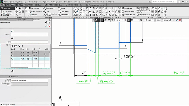
The application allows you to calculate dimensional chains for drawings and fragments in accordance with RD 50-635-87 "Methodical instructions. Dimensional chains. Basic concepts. Methods for Calculating Linear and Angular Circuits".
UNIT II
Four Exmples from Text Book will be given trainingOn software listed For the program Four problem will be given for self training with software to Trainee
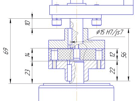
Dimension chain elements can be dimensioned or lined. The app allows you to perform calculations for horizontal, vertical, and oblique dimensions.
Calculations can be performed using the maximum-minimum method or the probabilistic-theoretic method.
Deviations are calculated for nominal dimensions in the range of 0... 10000 mm (GOST 25346-89, GOST 25347-82
Calculations can be performed using the maximum-minimum method or the probabilistic-theoretic method.
Deviations are calculated for nominal dimensions in the range of 0... 10000 mm (GOST 25346-89, GOST 25347-82
Dimension chains
Dimension chains
UNIT III
Four Exmples from Text Book will be given trainingOn software listed For the program Four problem will be given for self training with software to Trainee
For dimension chains in which at least one nominal dimension does not fit into the range, only nominal dimension values can be calculated.
Deviation calculations "A", "B", "C", "CD", "D", "E", "EF", "F", "FG", "G", "H", "JS", "K", "M", "N", "P", "R", "S", "T", "U", "V", "X", "Y", "Z", "Z", "ZA", "ZB", "ZC" with qualities 0-18 for shafts and holes
Deviation calculations "A", "B", "C", "CD", "D", "E", "EF", "F", "FG", "G", "H", "JS", "K", "M", "N", "P", "R", "S", "T", "U", "V", "X", "Y", "Z", "Z", "ZA", "ZB", "ZC" with qualities 0-18 for shafts and holes
UNIT IV
Four Exmples from Text Book will be given trainingOn software listed For the program Four problem will be given for self training with software to Trainee
KOMPAS 3D Application
Mechanical
UNIT I
Four Exmples from Text Book will be given trainingOn software listed For the program Four problem will be given for self training with software to Trainee
Four Exmples from Text Book will be given trainingOn software listed For the program Four problem will be given for self training with software to Trainee
Catalog Gearboxes
Catalog Gearboxes
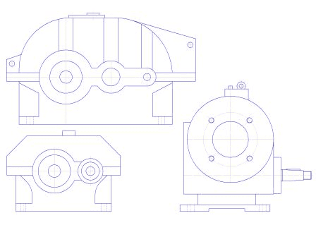
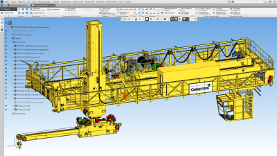
Catalog: Gearboxes are designed for the work of design engineers engaged in the design of electromechanical drives for various purposes.
UNIT II
Four Exmples from Text Book will be given trainingOn software listed For the program Four problem will be given for self training with software to Trainee
The appendix contains images and technical data of commercially produced general and special gearboxes, as well as information on manufacturers and suppliers.
The Catalog contains the following technical characteristics of gearboxes:
variants of transfer ratios,rated torque at the output shaft in continuous operation,Nominal radial loads on the input and output shafts,efficiency,gearbox weight,Climate options.
The Catalog contains the following technical characteristics of gearboxes:
variants of transfer ratios,rated torque at the output shaft in continuous operation,Nominal radial loads on the input and output shafts,efficiency,gearbox weight,Climate options.
Catalog Gearboxes
Catalog Gearboxes
Catalog Gearboxes
Catalog Gearboxes
UNIT III
Four Exmples from Text Book will be given trainingOn software listed For the program Four problem will be given for self training with software to Trainee
In addition, the values of nominal torques and loads under heavy, medium, light working conditions are indicated, as well as the parameters (dimensions, taper, number and modulus of teeth) of the input and output shafts of the gearboxes in various variants.
In the Catalog, you can also find information about the options for assembling gearboxes, select a gearbox according to the specified parameters (type, gear ratio, rated torque).
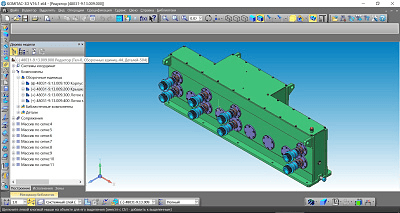
After selecting the necessary gearbox, the user can automatically receive its image in the drawing and transfer the relevant information to the specification.
In the Catalog, you can also find information about the options for assembling gearboxes, select a gearbox according to the specified parameters (type, gear ratio, rated torque).
After selecting the necessary gearbox, the user can automatically receive its image in the drawing and transfer the relevant information to the specification.
UNIT IV
Four Exmples from Text Book will be given trainingOn software listed For the program Four problem will be given for self training with software to Trainee
All information about gearboxes corresponds to the data of the official catalogs of manufacturers and suppliers (information about them is also available in the appendix).
Manufacturer: ASCON-Design SystemsLLC Requires for work: KOMPAS-GraphicSystem requirements correspond to the system requirements of KOMPAS-3D
Manufacturer: ASCON-Design SystemsLLC Requires for work: KOMPAS-GraphicSystem requirements correspond to the system requirements of KOMPAS-3D
KOMPAS 3D Application
Mechanical
UNIT I
Four Exmples from Text Book will be given trainingOn software listed For the program Four problem will be given for self training with software to Trainee
Four Exmples from Text Book will be given trainingOn software listed For the program Four problem will be given for self training with software to Trainee
Rolling bearings. Electronic Directory
Rolling bearings. Electronic Directory
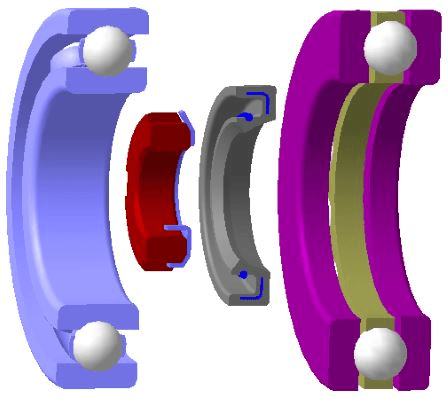
Designed to select rolling bearings and add them to a drawing or 3D model from a database of 19,000 component sizes. It allows you to calculate the performance parameters based on the operating conditions of the support nodes. Provides reference information on the accuracy and roughness of bearing components, friction, wear and lubrication processes. The handbook is intended for engineers and technicians in all industries
UNIT II
Four Exmples from Text Book will be given trainingOn software listed For the program Four problem will be given for self training with software to Trainee
"Rolling bearings. Electronic Handbook" will reduce the designer's time for searching for information, calculating support nodes and analyzing engineering solutions.
The database contains information on 19,000 standard bearing sizes of the 130 most common bore diameters in the bore diameter range d = (0.6 ... 1800) mm. The appendices of the handbook include characteristics and recommendations for the use of bearings.
The directory provides a search for Russian-made bearings by type and design, by performance parameters, by overall dimensions, by number. It is possible to decipher the values of the main and additional digits of the bearing number in accordance with GOST 3189.
The database contains information on 19,000 standard bearing sizes of the 130 most common bore diameters in the bore diameter range d = (0.6 ... 1800) mm. The appendices of the handbook include characteristics and recommendations for the use of bearings.
The directory provides a search for Russian-made bearings by type and design, by performance parameters, by overall dimensions, by number. It is possible to decipher the values of the main and additional digits of the bearing number in accordance with GOST 3189.
Rolling bearings. Electronic Directory
Rolling bearings. Electronic Directory
UNIT III
Four Exmples from Text Book will be given trainingOn software listed For the program Four problem will be given for self training with software to Trainee
In addition, the values of nominal torques and loads under heavy, medium, light working conditions are indicated, as well as the parameters (dimensions, taper, number and modulus of teeth) of the input and output shafts of the gearboxes in various variants.
In the Catalog, you can also find information about the options for assembling gearboxes, select a gearbox according to the specified parameters (type, gear ratio, rated torque).
After selecting the necessary gearbox, the user can automatically receive its image in the drawing and transfer the relevant information to the specification.
In the Catalog, you can also find information about the options for assembling gearboxes, select a gearbox according to the specified parameters (type, gear ratio, rated torque).
After selecting the necessary gearbox, the user can automatically receive its image in the drawing and transfer the relevant information to the specification.
UNIT IV
Four Exmples from Text Book will be given trainingOn software listed For the program Four problem will be given for self training with software to Trainee
The 2D/3D libraries provide rendering of 120 standard versions of bearings (according to the parameters from the database), spring thrust rings, spline nuts and lock washers, reinforced rubber cuffs in the medium of the KOMPAS-3D system.
The reference book allows you to perform calculations:
Reactions of supports and angles of rotation of the axes of bearing rings in supports;Diameter and number of rolling elements Dw, Z;Load capacities Co, C according to GOST 18854 and GOST 18855, respectively;Durability L10, Lna according to GOST 18855;Bearing set service life;Contact stresses of rolling elements with raceways (4th calculation options);Deformations in the contacts of the rolling elements with the raceways;Geometric parameters of the main types of threads;Caliber parameters;Connections with guaranteed interference.
The reference book allows you to perform calculations:
Reactions of supports and angles of rotation of the axes of bearing rings in supports;Diameter and number of rolling elements Dw, Z;Load capacities Co, C according to GOST 18854 and GOST 18855, respectively;Durability L10, Lna according to GOST 18855;Bearing set service life;Contact stresses of rolling elements with raceways (4th calculation options);Deformations in the contacts of the rolling elements with the raceways;Geometric parameters of the main types of threads;Caliber parameters;Connections with guaranteed interference.
KOMPAS 3D Application
Mechanical
UNIT I
Four Exmples from Text Book will be given trainingOn software listed For the program Four problem will be given for self training with software to Trainee
Four Exmples from Text Book will be given trainingOn software listed For the program Four problem will be given for self training with software to Trainee
Catalog Electric motors
Catalog Electric motors
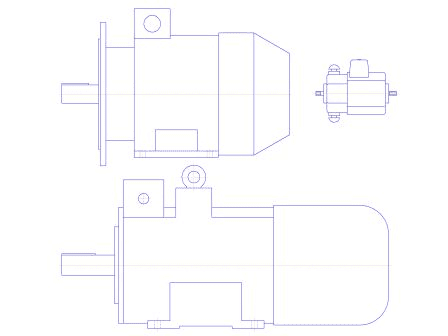
The application is aimed at use by designers engaged in the development of electromechanical drives for various applications.
UNIT II
Four Exmples from Text Book will be given trainingOn software listed For the program Four problem will be given for self training with software to Trainee
The application contains information about AC and DC electric motors and has 6 sections:
General purpose AC induction three-phase motors;Induction three-phase AC motors, explosion-proof;Asynchronous single-phase AC motors;Industrial DC motors with independent excitation;Stepper motors for various applications;Universal commutator motors.
General purpose AC induction three-phase motors;Induction three-phase AC motors, explosion-proof;Asynchronous single-phase AC motors;Industrial DC motors with independent excitation;Stepper motors for various applications;Universal commutator motors.
Catalog Electric motors
Catalog Electric motors
UNIT III
Four Exmples from Text Book will be given trainingOn software listed For the program Four problem will be given for self training with software to Trainee
The application contains the following data about electric motors:
Power;Synchronous shaft speed;Real speed of rotation taking into account sliding;Efficiency;Masse;The diameter of the output end of the shaft.
Power;Synchronous shaft speed;Real speed of rotation taking into account sliding;Efficiency;Masse;The diameter of the output end of the shaft.
UNIT IV
Four Exmples from Text Book will be given trainingOn software listed For the program Four problem will be given for self training with software to Trainee
A special module of the application — "Electric Motor Selection Wizard" — is designed for enlarged calculation of drive parameters and selection of a specific electric motor model based on them.
Also, the Catalog: Electric Motors has a built-in "Database Fill Wizard", which allows users to independently enter new brands of electric motors and their images into the library.
Manufacturer: ASCON-Design SystemsLLC Requires for work: KOMPAS-GraphicSystem requirements correspond to the system requirements of KOMPAS-
Also, the Catalog: Electric Motors has a built-in "Database Fill Wizard", which allows users to independently enter new brands of electric motors and their images into the library.
Manufacturer: ASCON-Design SystemsLLC Requires for work: KOMPAS-GraphicSystem requirements correspond to the system requirements of KOMPAS-
KOMPAS 3D Application
Mechanical
Mechanical - Construction
UNIT I
Four Exmples from Text Book will be given trainingOn software listed For the program Four problem will be given for self training with software to Trainee
Four Exmples from Text Book will be given trainingOn software listed For the program Four problem will be given for self training with software to Trainee
Document security system
Document security system
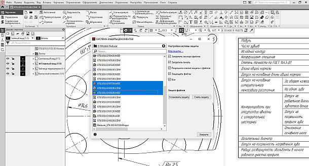
An application for protection against unauthorized access to electronic documents (drawings, specifications, three-dimensional models, etc.) developed in the KOMPAS-3D system.
UNIT II
Four Exmples from Text Book will be given trainingOn software listed For the program Four problem will be given for self training with software to Trainee
The principle of protection is based on file encoding. The code is set by the user when setting up the system before starting its use and is stored in the electronic key of the KOMPAS hardware protection. The system settings include allowing/disabling unprotection from files, enabling/disabling the export and printing of data. The security code and system settings can be changed at any time. The condition for changing the code, as well as changing other settings, is the correct entry of the code currently stored in the key. Thus, data confidentiality is ensured by the confidentiality of the code and the restriction of access to the hardware protection key.
Document security system
Document security system
UNIT III
Four Exmples from Text Book will be given trainingOn software listed For the program Four problem will be given for self training with software to Trainee
The work of a designer in KOMPAS-3D with the installed Security System is practically no different from ordinary work. However, if the Protect files option is enabled, any COMPASS document will be protected when saved: its subsequent opening will be possible only on those workstations where the Security System is installed, and the code stored in the key matches the code that protects the file.
UNIT IV
Four Exmples from Text Book will be given trainingOn software listed For the program Four problem will be given for self training with software to Trainee
These properties of the Security System in combination with organizational measures will allow the design organization to protect information from theft and differentiate access to information of different levels of secrecy.
Manufacturer: ASCON-Design SystemsLLC Requires for work: KOMPAS-3DSystem requirements correspond to KOMPAS-3D system requirements
Manufacturer: ASCON-Design SystemsLLC Requires for work: KOMPAS-3DSystem requirements correspond to KOMPAS-3D system requirements