Industry Projects
Mechanical Projects Entertainment Equipment
Internship Program-Project Program-Product Dev, Program



UNIT I
Four Exmples from Text Book will be given trainingOn software listed For the program Four problem will be given for self training with software to Trainee
The calculation of the "Biorobot" attraction was carried out by order of the individual entrepreneur Dzhikiya G.V.
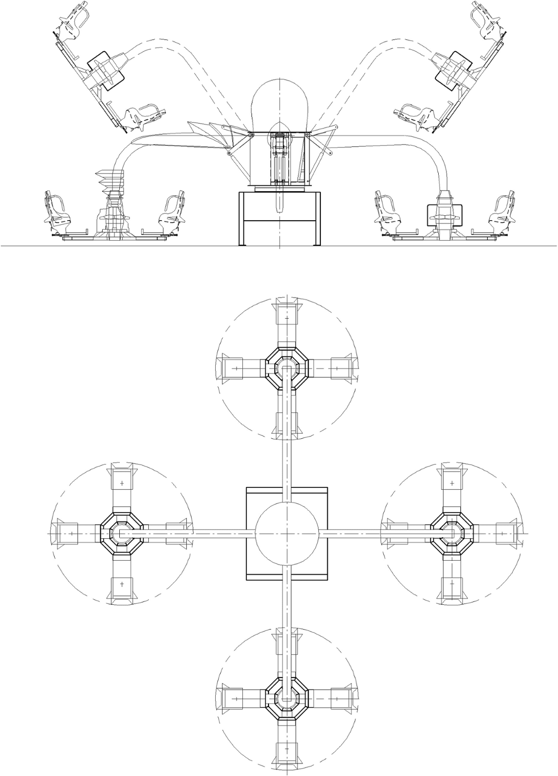
The attraction is a device that provides the general rotational movement of the platforms with seats (freely rotating), as well as their lifting and lowering. The attraction is intended for operation in parks and other areas of mass recreation of the population, for the entertainment of children over 14 years old and adults. The attraction is foundationless.
The purpose of the calculation is to analyze the structure of the "Biorobot" attraction for strength, rigidity and stability under the action of design loads.
The calculation of the attraction structure is carried out in accordance with the requirements:
GOST R 52170 – 2003;GOST R 53130 – 2008;GOST 27751-88;SP 16.13330.2011.
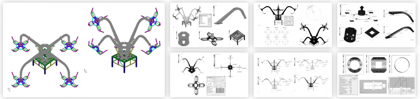
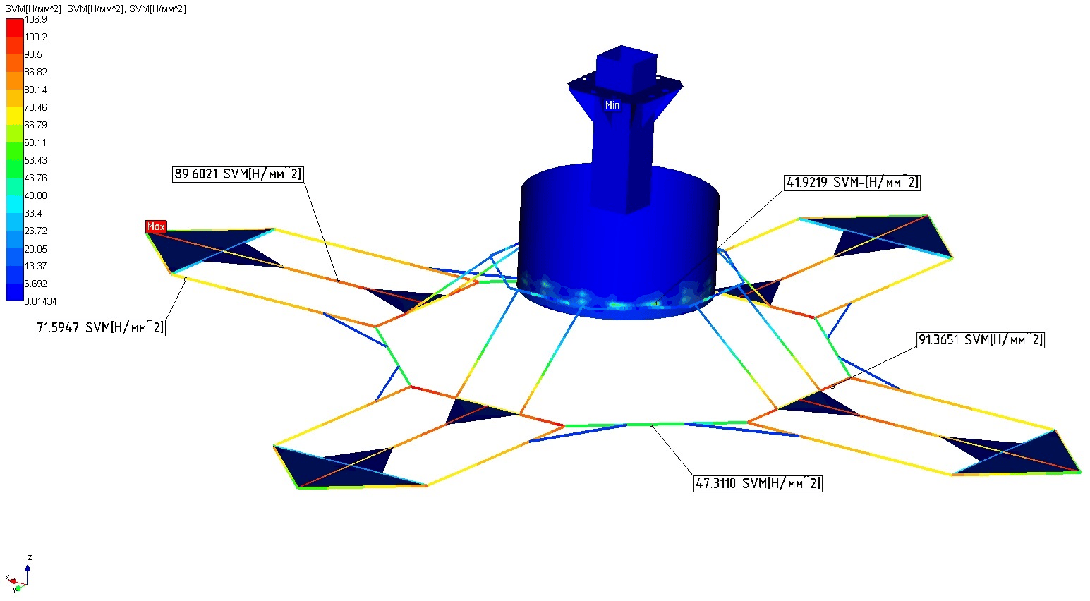
The strength calculation of the attraction structure was carried out using the APM Structure3D module, which is part of the APM WinMachine system.
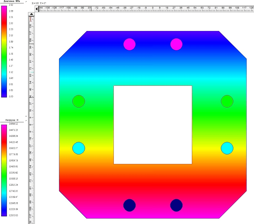
The axes were calculated using APM Shaft, the bolted connections were calculated using APM Joint. These modules are also part of the APM WinMachine system.
UNIT IV
Four Exmples from Text Book will be given trainingOn software listed For the program Four problem will be given for self training with software to Trainee
Based on the results of the calculations, the following conclusions were made:
Analysis of the results of the static calculation shows that at the given design loads, the equivalent stresses arising in the elements of the attraction do not exceed the yield strength (design resistance) of the materials used, i.e. the required strength is provided.It has been established that under the action of design loads in all cases of loads, the rigidity of the structural shape of the attraction is ensured. The resulting movements of the elements of the attraction do not exceed the permissible ones.
Summarizing the results obtained, it can be concluded that the structure of the attraction is able to carry the loads applied to it, corresponding to the operating conditions, and does not require additional measures to increase the strength characteristics.
The work carried out showed the applicability of the APM WinMachine software package for solving complex problems of strength analysis of amusement rides.


UNIT II
Four Exmples from Text Book will be given trainingOn software listed For the program Four problem will be given for self training with software to Trainee
nput
Depending on the duration of action, it is necessary to distinguish between permanent and temporary loads on the elements of the attraction.
The constant loads of the attraction include the self-weight of the supporting structure, equipment, and the weight of the seats.
Temporary loads include passenger weight, gyroscopic, dynamic, wind, snow, and temperature.
As a result, the calculation of the attraction was carried out for the following loads:
- Dead weight of the structure;
- The weight of the visitors of the attraction;
- Inertia forces of rotating parts of the structure;
- Inertia forces of visitors;
- Wind.
The design is designed for both full load and partial load operation. The calculation of the structure for one-way loading was carried out for the case when the seats on 1/4 or 3/4 of the perimeter of the attraction are occupied.
With the uniform rotation of the ride, centrifugal inertia forces occur. When each cabin of the attraction is fully loaded, they form a balanced system of forces. If the attraction is not fully loaded by passengers, the system of inertia forces is not balanced. In this case, the load-bearing elements of the structure experience an additional dynamic load.
According to the terms of reference, the operation of the attraction in rain, snow and wind of more than 10 m/s is prohibited. In this regard, snow loads were neglected, and the design wind pressure on the structure was determined in accordance with GOST R 52170-2003.
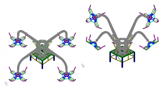
Due to the different angle of inclination of the platforms to the horizon during the operation of the attraction, the initial (lower) and final (upper) positions of the platforms were considered.
UNIT III
Four Exmples from Text Book will be given trainingOn software listed For the program Four problem will be given for self training with software to Trainee
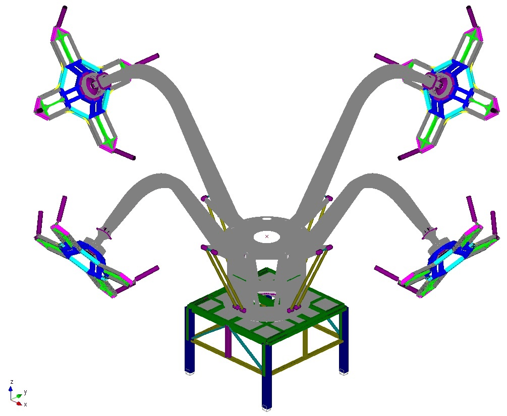
The calculation model of the attraction was formed on the basis of drawings sent by the Customer. The attraction is a foundationless collapsible structure. The structural elements were modeled with plate and rod end elements.
The member elements of the model have the status of beam elements capable of absorbing all types of deformation (tension/compression, bending, torsion). The assignment of cross-sections for them was carried out in accordance with the available design documentation for the product. The geometric characteristics of the sections were defined from the standard section library.
Due to the fact that the calculation model did not take into account the weight of fasteners, welded joints, as well as some drive elements, the weight was taken into account with a premium of 20%.
The seat mass is applied as a force to the seat centre of gravity assembly. All forces coming to the center of gravity of the seat (including inertial forces) were transmitted by connecting the seat center of gravity with the seat axis by rigid inserts. In a similar way, the weight from the passengers and the force of inertia were applied.
Calculation results
The design was carried out for the most adverse effects of the loads.
The following calculations were made for the attraction:
Calculation of the static strength of the ride;Assessment of the stiffness and ultimate flexibility of structural elements;Calculation of shape stability;Calculation for the stability of the position;Structural fatigue analysis;Strength Calculation of Critical Components of the Ride:bolted connections;finger connections;axles.
As a result of calculations for static strength, support reactions, internal force factors, stresses, deformations arising in structural elements under various combinations of loads were obtained.
When assessing the reliability and performance of the attraction, the calculation for fatigue and the analysis of connections and other critical components were carried out.
The calculation of the attraction for stability was carried out for the case of its overturning, sliding and lifting.
The ultimate stiffness and ultimate flexibility were evaluated for each type of element in the most loaded area of the structure.
An assessment of fatigue in the occurrence of repeatedly acting moving loads from the rotation of the attraction itself and from the rotation of the seats is carried out.