Industry Projects
Mechanical Projects Aviation
Aircraft Cabin
Internship Program-Project Program-Product Dev, Program

APM WINMACHINE APM CIVIL APM FEM

UNIT I
Four Exmples from Text Book will be given trainingOn software listed For the program Four problem will be given for self training with software to Trainee
Aircraft cockpit
LLC STC APM performed a strength calculation of the cockpit load-bearing structure to substantiate the possibility of its use as an aircraft cockpit after retrofitting it with instrumentation, installing a C-30 centrifuge on the arm and carrying out work in it during rotation with an overload of up to 10g and up to 15g.
Project objectives: calculation of strength characteristics (permissible loads) of the cabin structure at the places and points of attachment of the equipment placed on it.
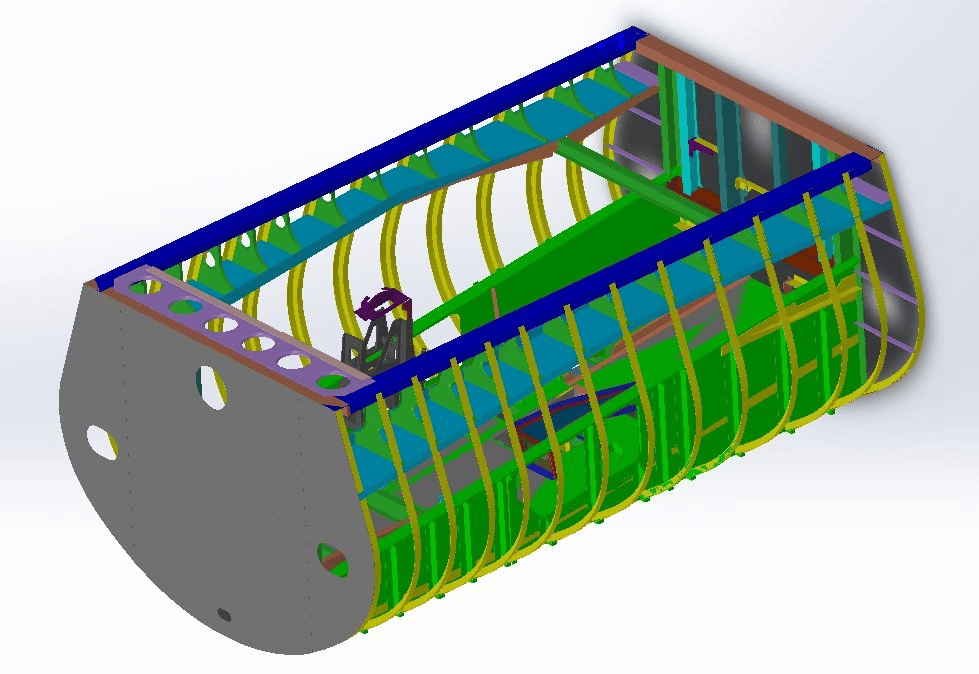
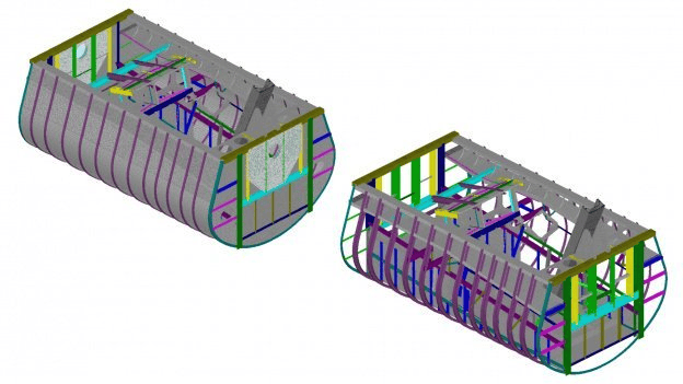
The product is a metal cabin with instrumentation reinforced in it. The load-bearing frame is formed by spars and frames, sheathed with duralumin sheets (sheathing).
Spars (elements of the longitudinal frame set) absorb mainly longitudinal forces and bending moments, and also connect the elements of the transverse frame - frames.
Frames are elements of the transverse set of the frame, give the cabin a given cross-sectional shape, provide lateral rigidity, and also absorb local loads and reinforce the rigid skin.
The sheathing is made of aluminum alloy sheets and is attached to the frame elements. The skin sheets are connected to each other along the frames end-to-end.
Installation method: hinged fastening to the truss of the Ts-30 centrifuge.
The calculation was carried out using the software product - CAD/CAE "APM WinMachine System for Computer-Aided Calculation and Design of Mechanical Equipment and Structures".
LLC STC APM performed a strength calculation of the cockpit load-bearing structure to substantiate the possibility of its use as an aircraft cockpit after retrofitting it with instrumentation, installing a C-30 centrifuge on the arm and carrying out work in it during rotation with an overload of up to 10g and up to 15g.
Project objectives: calculation of strength characteristics (permissible loads) of the cabin structure at the places and points of attachment of the equipment placed on it.
The product is a metal cabin with instrumentation reinforced in it. The load-bearing frame is formed by spars and frames, sheathed with duralumin sheets (sheathing).
Spars (elements of the longitudinal frame set) absorb mainly longitudinal forces and bending moments, and also connect the elements of the transverse frame - frames.
Frames are elements of the transverse set of the frame, give the cabin a given cross-sectional shape, provide lateral rigidity, and also absorb local loads and reinforce the rigid skin.
The sheathing is made of aluminum alloy sheets and is attached to the frame elements. The skin sheets are connected to each other along the frames end-to-end.
Installation method: hinged fastening to the truss of the Ts-30 centrifuge.
The calculation was carried out using the software product - CAD/CAE "APM WinMachine System for Computer-Aided Calculation and Design of Mechanical Equipment and Structures".
UNIT IV
Four Exmples from Text Book will be given trainingOn software listed For the program Four problem will be given for self training with software to Trainee
Results of the completed project
Based on the results of the strength calculation of the cab structure, the following conclusions can be drawn:
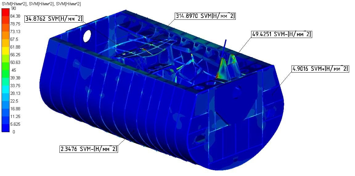
Based on the analysis of finite element models, it was established that the stress-strain state of the structure under the action of design loads has a heterogeneous character, which most significantly depends on the value of overload, weight and location of instrumentation in the cabin structure. The contribution of the self-weight load to the overall picture of the VAT of the product is insignificant, its maximum impact is estimated within 10%. Therefore, the nature of the distribution of internal forces, stresses and deformations depends to a greater extent on the position of the structural element relative to the axis of rotation of the cab.The stress state of the product's load-bearing system is characterized by the presence of concentrations of equivalent stresses, the occurrence of which is associated with the presence of geometric and "model" concentrators in the calculation models, which create features of the stress state in their vicinity. It should be noted that stress concentrations are local. The distribution of equivalent voltages outside these zones does not depend on their maximum level. In this regard, the presence of characteristic concentration zones in the calculation model can be neglected, and the mechanical state of the structure can be evaluated by the highest level of stresses acting outside them. In the working condition of the product (at overloads not exceeding 15g), the value of equivalent stresses arising in the elements of the reinforced structure
Based on the results of the strength calculation of the cab structure, the following conclusions can be drawn:
Based on the analysis of finite element models, it was established that the stress-strain state of the structure under the action of design loads has a heterogeneous character, which most significantly depends on the value of overload, weight and location of instrumentation in the cabin structure. The contribution of the self-weight load to the overall picture of the VAT of the product is insignificant, its maximum impact is estimated within 10%. Therefore, the nature of the distribution of internal forces, stresses and deformations depends to a greater extent on the position of the structural element relative to the axis of rotation of the cab.The stress state of the product's load-bearing system is characterized by the presence of concentrations of equivalent stresses, the occurrence of which is associated with the presence of geometric and "model" concentrators in the calculation models, which create features of the stress state in their vicinity. It should be noted that stress concentrations are local. The distribution of equivalent voltages outside these zones does not depend on their maximum level. In this regard, the presence of characteristic concentration zones in the calculation model can be neglected, and the mechanical state of the structure can be evaluated by the highest level of stresses acting outside them. In the working condition of the product (at overloads not exceeding 15g), the value of equivalent stresses arising in the elements of the reinforced structure
UNIT II
Four Exmples from Text Book will be given trainingOn software listed For the program Four problem will be given for self training with software to Trainee
Calculation model
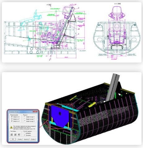
The construction of a finite element model to calculate the strength of the bench cabin structure, as well as the equipment fastening points, is carried out in the APM Structure3D module.
When building the calculation model, rod (beam), three- and four-node plate, six- and eight-node volumetric finite elements were used.
The internal connections of the model simulated the conditions for connecting individual structural elements of the cabin. Approximation to the real conditions of connection of such structural elements was achieved by introducing fictitious (non-deformable) rods into the calculation model and removing restrictions on certain degrees of freedom from them.
All connections in the FE model are central, i.e. the connection is carried out through the centers of gravity of the sections of the corresponding elements.
The design load is determined according to the ToR and includes constant (from the action of gravitational forces) and temporary (from the action of inertial forces) components.
The supporting structure of the cabin is under the action of distributed vertical and horizontal force systems. Vertical forces are created by the own weight of the structure, equipment, and pilot. The horizontal load on the structure is created by the inertial forces that occur when the car rotates.
Uniform rotation of the cab is accompanied by the emergence of centrifugal force of inertia. At the same time, the load-bearing elements of the structure experience an additional dynamic load.
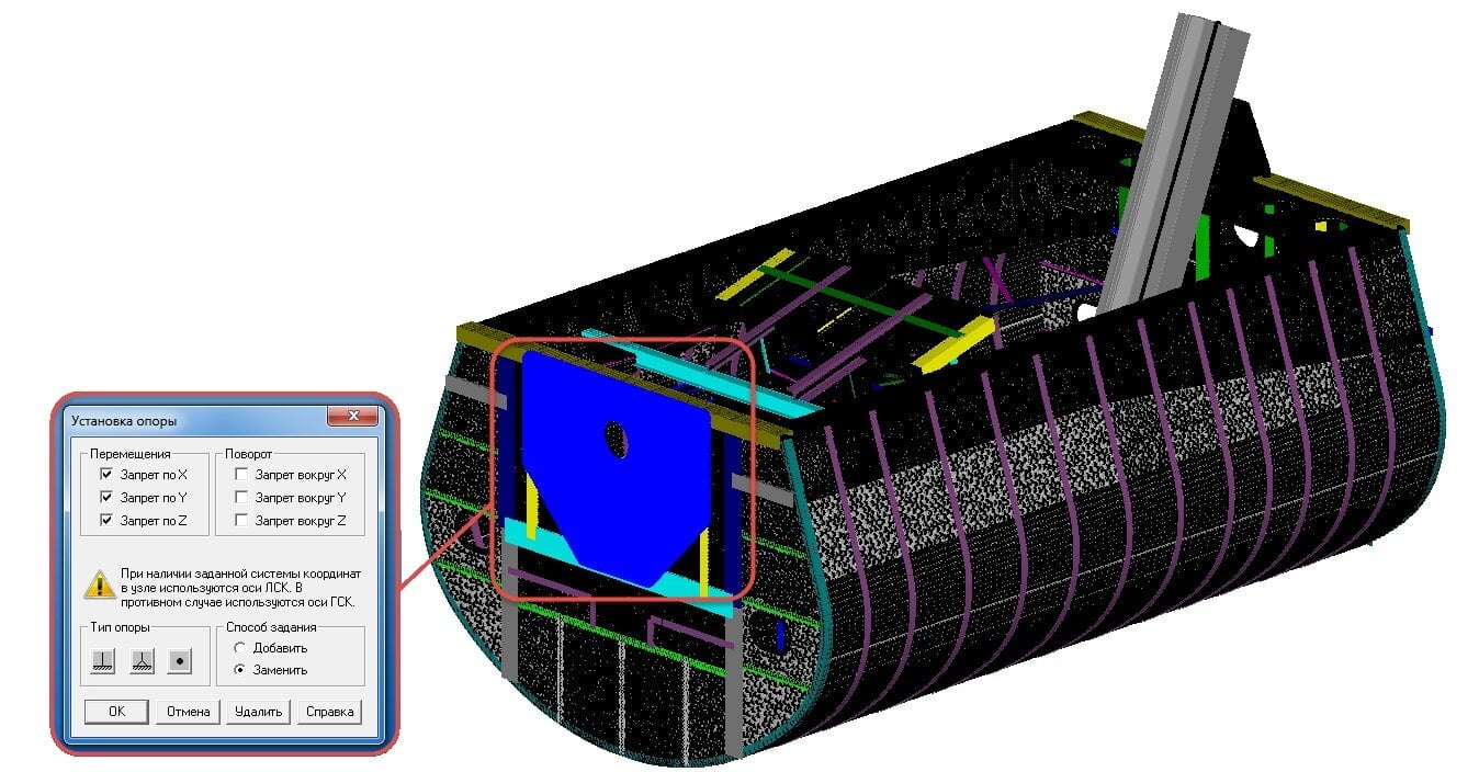
Schematization of the conditions for fixing the model involves the imitation of restrictions imposed by external and internal connections on the position of the elastic system as a whole and individual structural elements. The imposition of external relations is determined by the TOR. When modeling the behavior of the supporting structure, the option of fixing it on the arm of the C-30 centrifuge is considered. External relations of the system were reproduced by setting restrictions on the movement of supports relative to the global Cartesian coordinate system (GCS model). The fixation of the calculation model was carried out by imposing restrictions on the linear displacements of the nodal points of the supporting elements.
The construction of a finite element model to calculate the strength of the bench cabin structure, as well as the equipment fastening points, is carried out in the APM Structure3D module.
When building the calculation model, rod (beam), three- and four-node plate, six- and eight-node volumetric finite elements were used.
The internal connections of the model simulated the conditions for connecting individual structural elements of the cabin. Approximation to the real conditions of connection of such structural elements was achieved by introducing fictitious (non-deformable) rods into the calculation model and removing restrictions on certain degrees of freedom from them.
All connections in the FE model are central, i.e. the connection is carried out through the centers of gravity of the sections of the corresponding elements.
The design load is determined according to the ToR and includes constant (from the action of gravitational forces) and temporary (from the action of inertial forces) components.
The supporting structure of the cabin is under the action of distributed vertical and horizontal force systems. Vertical forces are created by the own weight of the structure, equipment, and pilot. The horizontal load on the structure is created by the inertial forces that occur when the car rotates.
Uniform rotation of the cab is accompanied by the emergence of centrifugal force of inertia. At the same time, the load-bearing elements of the structure experience an additional dynamic load.
Schematization of the conditions for fixing the model involves the imitation of restrictions imposed by external and internal connections on the position of the elastic system as a whole and individual structural elements. The imposition of external relations is determined by the TOR. When modeling the behavior of the supporting structure, the option of fixing it on the arm of the C-30 centrifuge is considered. External relations of the system were reproduced by setting restrictions on the movement of supports relative to the global Cartesian coordinate system (GCS model). The fixation of the calculation model was carried out by imposing restrictions on the linear displacements of the nodal points of the supporting elements.
UNIT III
Four Exmples from Text Book will be given trainingOn software listed For the program Four problem will be given for self training with software to Trainee
alculation results
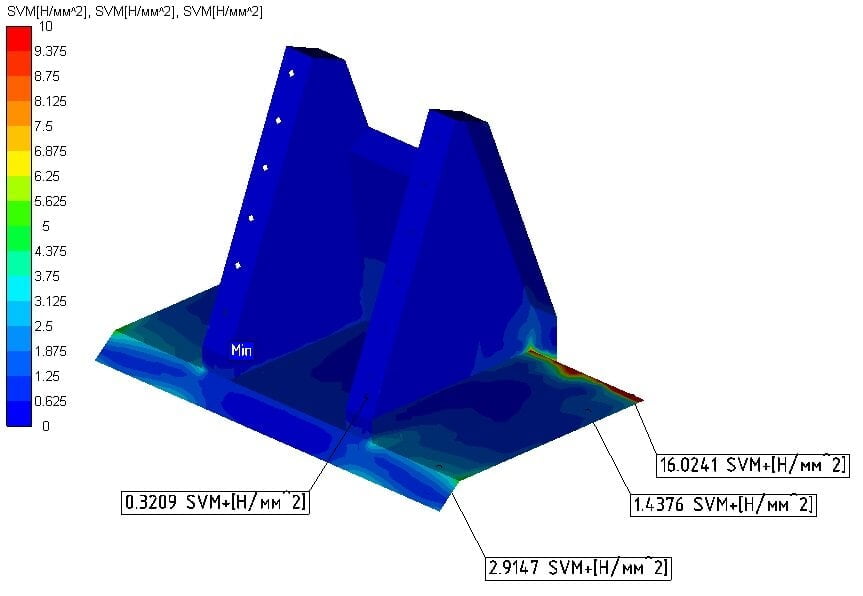
In the course of the static analysis of the calculation model, the following were determined: support reactions, internal force factors, stresses and deformations arising in the structural elements, estimates of its static strength were obtained.
The values of internal force factors in the model nodes obtained from the results of static analysis were used as initial data when performing verification calculations of joints for static strength.
Based on the results of the strength calculation, a conclusion is given on the possibility of further safe operation of the cabin on the Ts-30 centrifuge, after routine maintenance on it, as well as recommendations for strengthening the critical components of the product.
In the course of the static analysis of the calculation model, the following were determined: support reactions, internal force factors, stresses and deformations arising in the structural elements, estimates of its static strength were obtained.
The values of internal force factors in the model nodes obtained from the results of static analysis were used as initial data when performing verification calculations of joints for static strength.
Based on the results of the strength calculation, a conclusion is given on the possibility of further safe operation of the cabin on the Ts-30 centrifuge, after routine maintenance on it, as well as recommendations for strengthening the critical components of the product.