Industry Projects
Mechanical Projects Lifting and Conveying Equipment
Tower Crane
Internship Program-Project Program-Product Dev, Program



UNIT I
Four Exmples from Text Book will be given trainingOn software listed For the program Four problem will be given for self training with software to Trainee
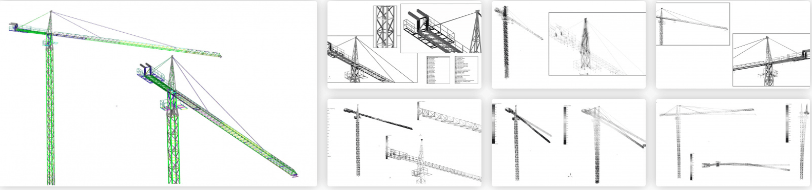
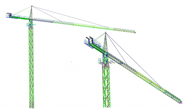
The calculation of the stationary tower crane was carried out by order of Tsentrenergomekhanizatsiya LLP.
STC APM has completed a set of design works for a stationary tower crane. The crane includes 10 sections of 3 meters each with a maximum length of 50 m.
The purpose of the work: to determine the characteristics of the tower crane for further certification in the relevant authorities for the operation of the crane on the territory of Kazakhstan
UNIT IV
Four Exmples from Text Book will be given trainingOn software listed For the program Four problem will be given for self training with software to Trainee
In the calculation, the maximum equivalent Mises stress in a number of load case combinations exceeded the yield strength of the material. Moreover, this excess of yield strength is observed in the same place.
In addition, in combinations of load cases with seismic loading, the factor of safety does not exceed the recommended one.
As a result, it was necessary to carry out calculations when replacing cross-sections in which the strength conditions are not met, and it was also necessary to reduce the seismicity of the crane installation area.

UNIT II
Four Exmples from Text Book will be given trainingOn software listed For the program Four problem will be given for self training with software to Trainee
Analysis of the results of the static calculation showed that at the specified design loads, the equivalent stresses arising in the structural elements of the gantry crane do not exceed the yield strength of the materials used, i.e. the required strength is provided.
The maximum deflections of the gantry crane structure arising from external loads also do not exceed the permissible limit. That is, the necessary rigidity of the load-bearing frame is ensured.
Checking the load-bearing capacity of the most loaded structural element (the lower flange of the bridge beam) on a solid model showed that the stresses and displacements occurring in the
UNIT III
Four Exmples from Text Book will be given trainingOn software listed For the program Four problem will be given for self training with software to Trainee
The model of the steel structure of the tower crane was created in accordance with the assembly and detail drawings submitted by the Customer, using rod and plate (shell) finite elements.
The links between the structural elements are rigid. The connections of the boom and counterweight sections to the head were modeled by connections with one rotational degree of freedom. The connections at the base of the 7.5-meter section of the tower are absolutely rigid (supports), they do not have degrees of freedom relative to the corresponding axes of the global coordinate system.
Connections in the structural model are central, i.e. the connection is carried out through the centers of gravity of the sections of the corresponding elements.
When creating the analysis model, the welds were not explicitly modeled.
The application of loads was carried out in stages, by creating load cases, each of which was responsible for a particular force factor.
The metal structure of the crane was modeled only by load-bearing elements. In this regard, the nominal weight of the crane was "gained" by increasing the density of the corresponding units.
The calculation also took into account the weight of individual crane units (mounting section, cabin, etc.) in the static calculation simulated by the forces in the corresponding nodes, and for the calculation with seismic action – by masses.