Industry Projects
Construction Projects
Timber Structure Frame Panel
Internship Program-Project Program-Product Dev, Program



UNIT III
Four Exmples from Text Book will be given trainingOn software listed For the program Four problem will be given for self training with software to Trainee
The static stress-strain state analysis and stability analysis were carried out in a geometrically and physically linear setting using the finite element method in the APM Structure3D module.
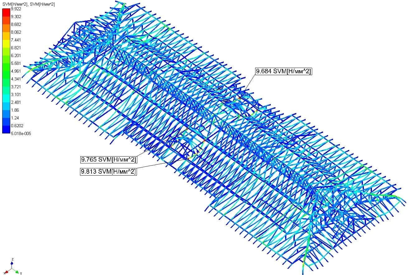
5 static calculations of the building structure for the main load combinations were performed. Maps of the stressed and deformed state of the structure under the corresponding loading options are obtained.
From the analysis of the results of the stress state of the roof frame, building frame and floors, it can be seen that the highest equivalent Mises stresses occur in the elements of the upper chord of roof trusses, and do not exceed the design resistance. This allows us to conclude that the strength condition is met.
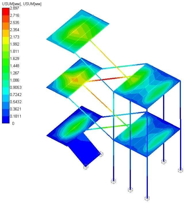
The maximum total displacements of the building elements do not exceed the permissible ones, which satisfies the stiffness condition.The calculation of the basement floor is given separately. For the overlap model, the equivalent Mises stresses do not exceed the allowable stresses, which satisfies the strength condition.
The maximum total displacements do not exceed the norm, which satisfies the stiffness condition.An analysis of the strength and rigidity of the staircase structure was also carried out.
The safety factor of the building structure is 3, therefore, the stability condition is satisfied.
The ultimate stiffness factor in the XOZ plane for the frame racks of wall panels and floor beams is greater than 1. This is due to the fact that the calculation does not take into account the influence of the stiffness of OSB-3 sheathing, made on both sides of wall panels and floors. The rest of the utilization factors according to the above criteria of strength and stability do not exceed 1, therefore, it can be concluded that the load-bearing conditions for them are met.
UNIT I
Four Exmples from Text Book will be given trainingOn software listed For the program Four problem will be given for self training with software to Trainee
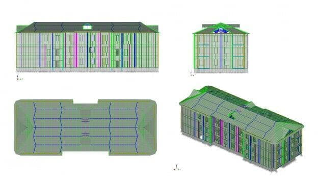
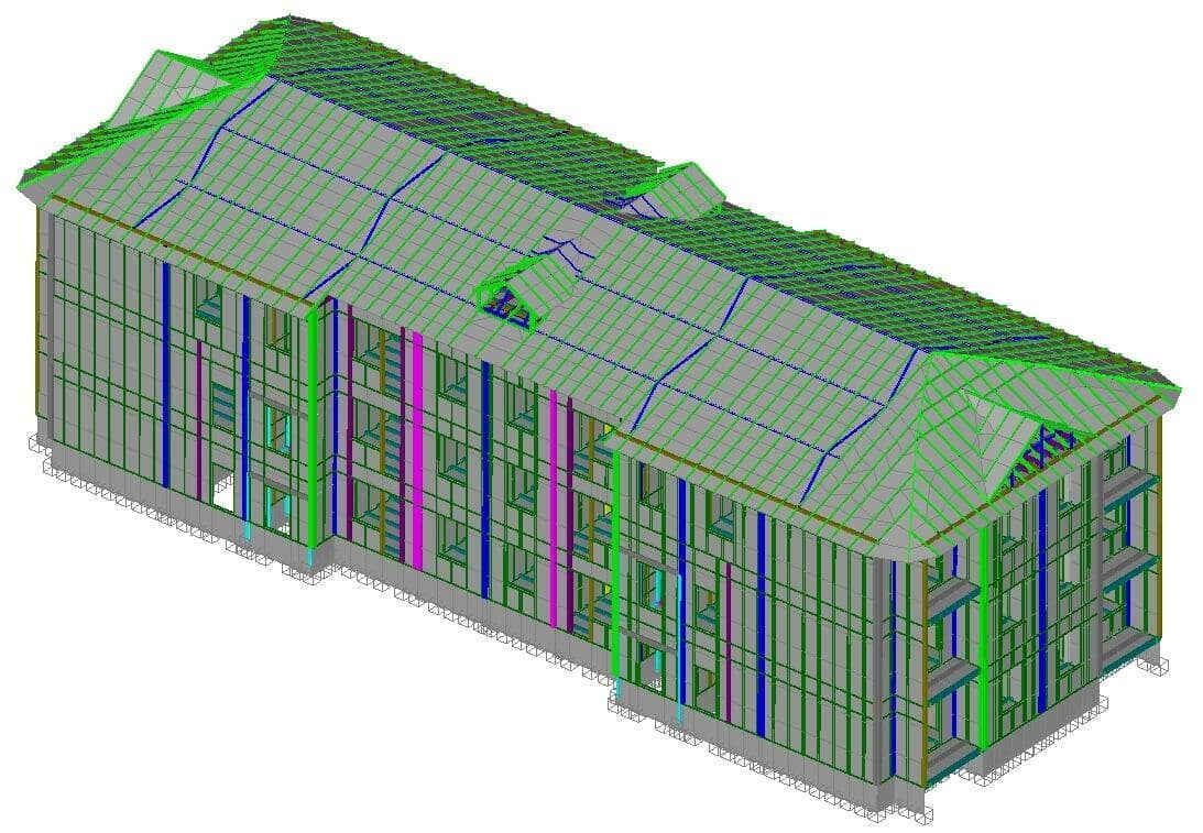
The company STC "APM" carried out a strength calculation of a 3-storey 2-entrance frame-panel residential building under the action of the main combination of loads.
Geometric dimensions of the building in the plan: length 35,690 mm, width 13,240 mm.
The main part of the building (walls and ceilings) is a wooden frame. The posts of the outer and inner walls are made of wood. The stair posts are made of steel pipes. The exterior walls are lined with porcelain tiles.
The calculation was carried out in the APM CivilEngineering software product.
UNIT IV
Four Exmples from Text Book will be given trainingOn software listed For the program Four problem will be given for self training with software to Trainee
The analysis of the structure showed that the strength of the frame-panel residential building is ensured.
The work carried out showed the applicability of the APM Civil Engineering software package for solving the problems of strength analysis of wooden structures.

UNIT II
Four Exmples from Text Book will be given trainingOn software listed For the program Four problem will be given for self training with software to Trainee
The model of the building structure was built in accordance with the terms of reference.
The structure of the building was modeled using rod and shell finite elements.
Connections in the building model are central, i.e. the connection is carried out through the centers of gravity of the sections of the corresponding elements.
The model has both rigid connections and hinged ones with one rotational degree of freedom.
The base links (supports) have three rotational degrees of freedom relative to the corresponding axes of the global coordinate system.
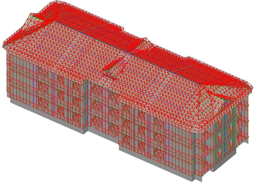
The calculated load values were set in accordance with the terms of reference.
List of design loads:
1) Own weight (own weight of the structure, weight of coverings, load from the weight of the staircase).
Due to the fact that the wall panels, floor panels, attic panels were modeled with a single slab, the dead weight was taken into account by increasing their density to an equivalent one.
2) Floor Payload
The distributed standard load on floor slabs is 1500 N/sq.m.The distributed standard load on corridor floors and staircase is 3000 N/sq.m.The distributed standard load on the attic floor is 700 N/sq.m.The distributed standard load on the balcony is 2000 N/sq.m.
3) Snow load according to SNiP 2.01.07-85*
4) Wind load according to SNiP 2.01.07-85*