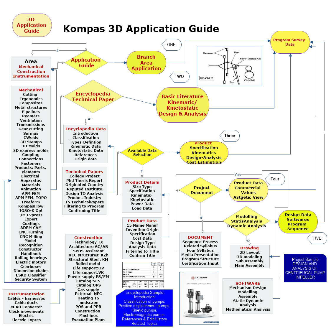
Kompas 3D Mechanical Application II
Women Graduates are trained with basics in Industry application from basic science Mathematics, Physics, Chemistry
Training in application Software by Industry Professional, to train others with preparation as TRAINER to empower.
Empowering areas are ACADEMIC SERVICE-ENTREPRENEURSHIP-DESIGN SERVICE-INDUSTRIES-SOCIAL ENGINEERING
Syllabus Program-Internship Program-Project Program-Product Dev, Program
KOMPAS 3D Application

Mechanical
Four Exmples from Text Book will be given trainingOn software listed For the program Four problem will be given for self training with software to Trainee
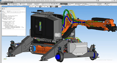
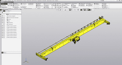
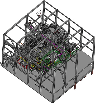
Equipment: Metal structures
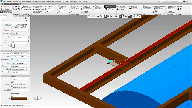
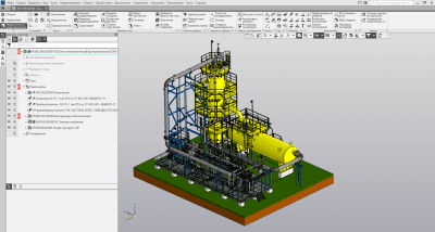
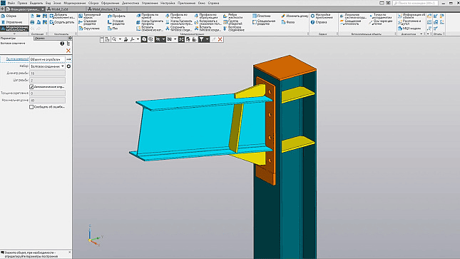
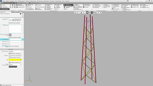
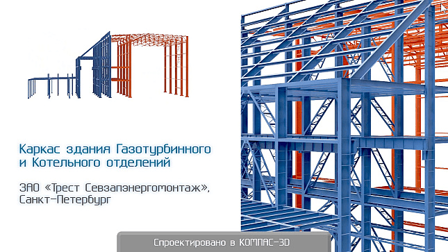
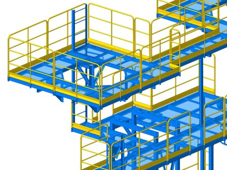
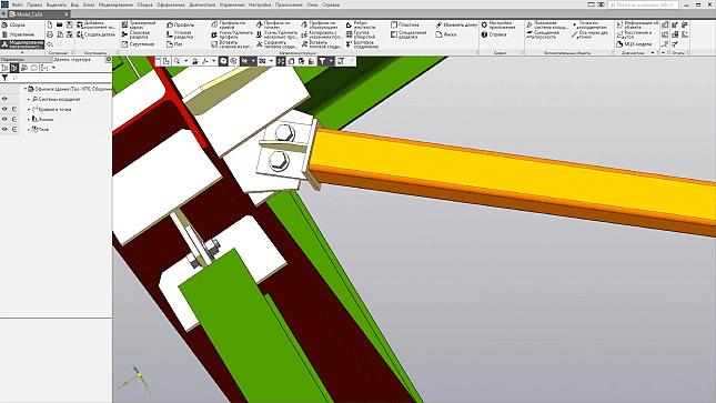
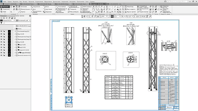
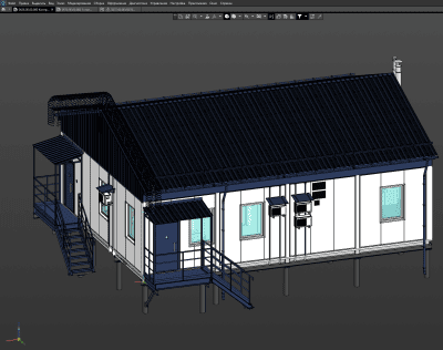
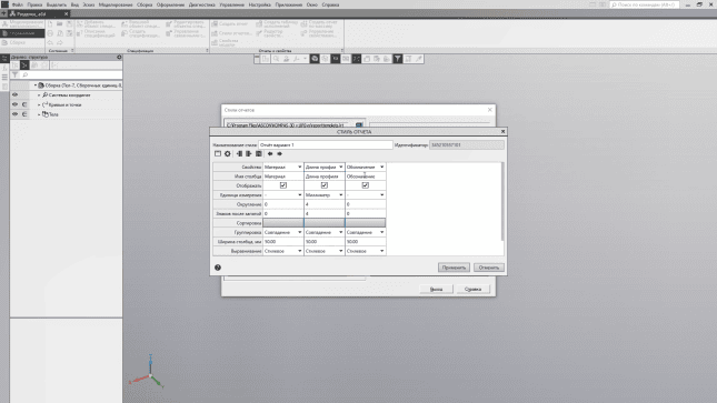
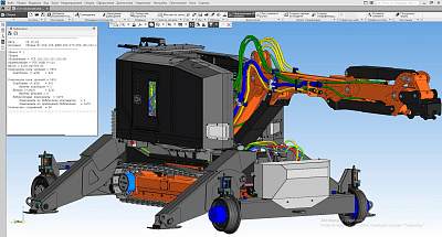
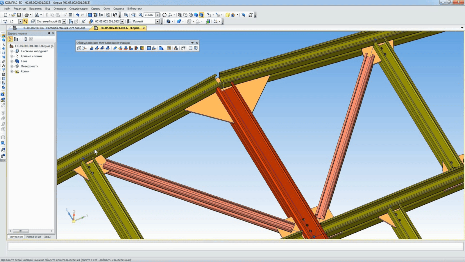
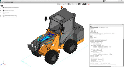
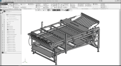
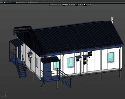
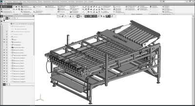
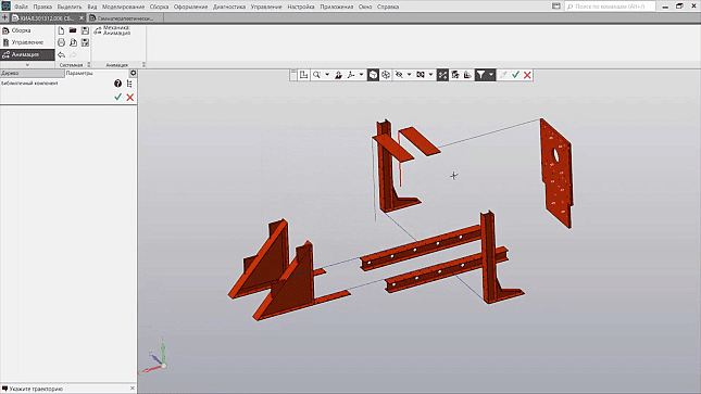
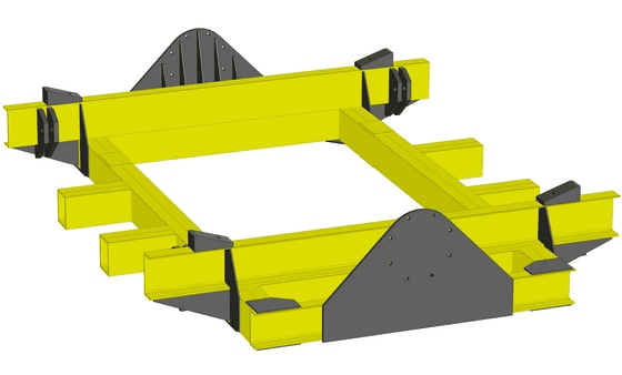
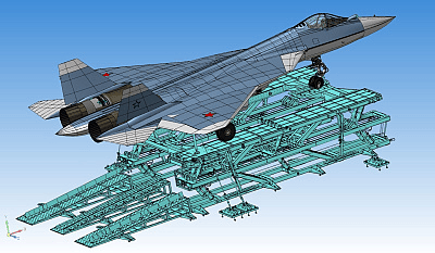
The creation of a metal structure in the application begins with the construction of a Three-Dimensional Frame - geometric axes, which are a sketch of the structure. After that, a profile is assigned for each of the axes, which is selected from the "Materials and Assortments for COMPASS" application (requires a separately paid license). For the convenience of building and editing the metal structure, the application implements the Feature Points mechanism, which allows you to set the length and angle of rotation of the profile directly in the construction window. If you change the Three-dimensional frame, the metal structure will rebuild automatically.
Equipment: Metal structures
KOMPAS 3D Application
Mechanical
Four Exmples from Text Book will be given trainingOn software listed For the program Four problem will be given for self training with software to Trainee
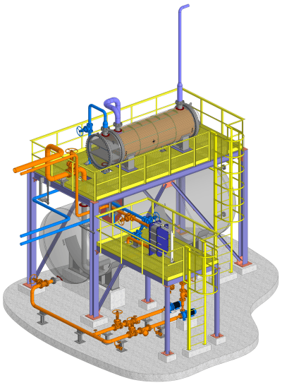
Equipment: Pipelines
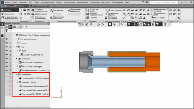
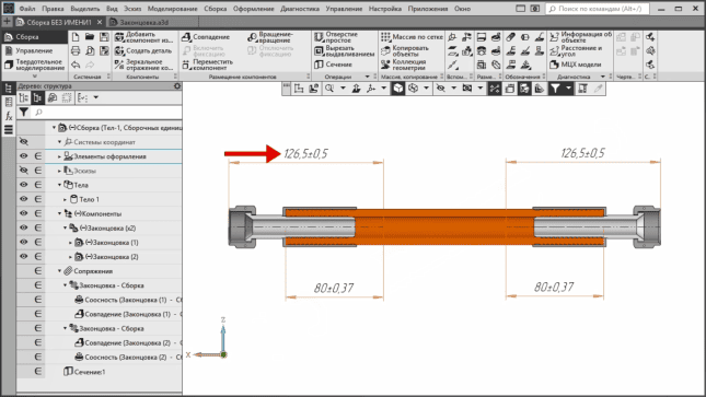
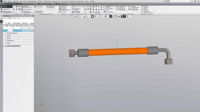
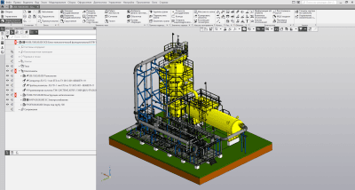
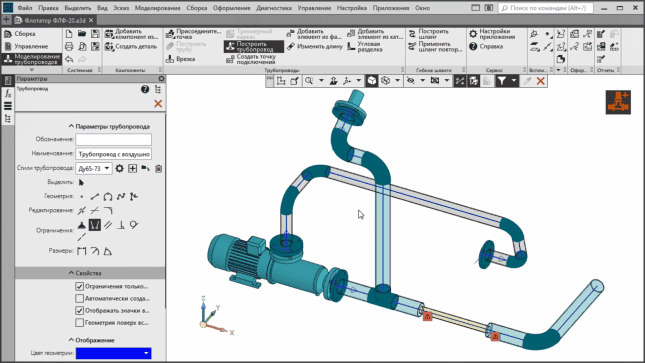
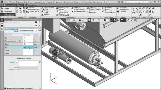
In the process of creating a trajectory, the pipeline itself is automatically built, for setting the parameters of which a special panel is provided. Depending on the geometry of the centerline, the piping parts are automatically picked. If the trajectory makes a turn, a branch or bend of the pipe is automatically placed, and if the pipe intersects with another pipe, then a tee or tie-in appears in this place. Turning radii will be determined automatically depending on the selected pipe diameter.
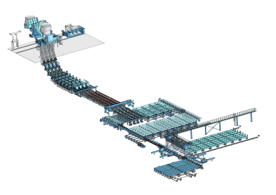
Equipment: Pipelines

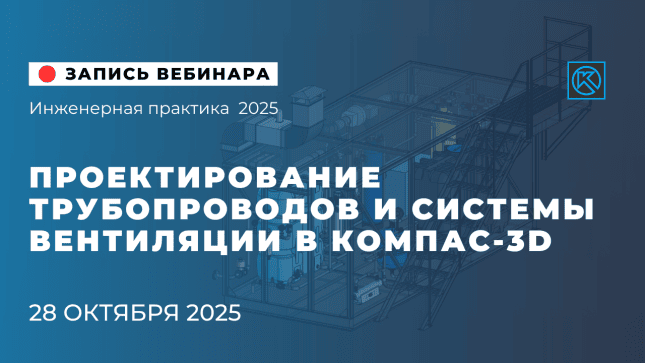
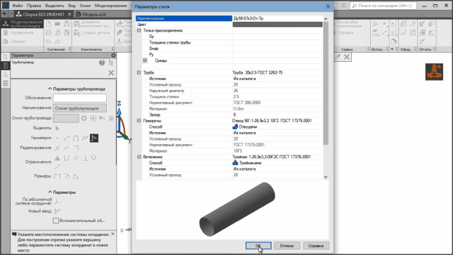
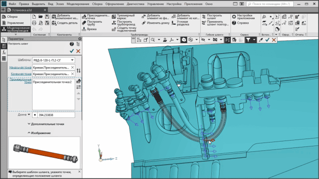
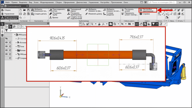
The application also allows you to place piping elements (shut-off valves, flanges, filters, valves, etc.), trim pipe ends, edit pipe diameter and wall thickness.
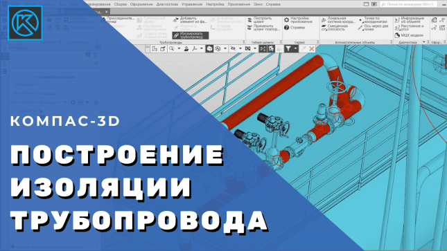
You can use both components from the application catalog and components from the Standard Products Library as parts and fittings for piping. The work of the designer is greatly facilitated in terms of drawing up project documentation. All elements added to the model are automatically transferred to drawings, specifications, reports.
KOMPAS 3D Application
Mechanical
Four Exmples from Text Book will be given trainingOn software listed For the program Four problem will be given for self training with software to Trainee
Equipment: Reamers
A separately paid license is required to use the application
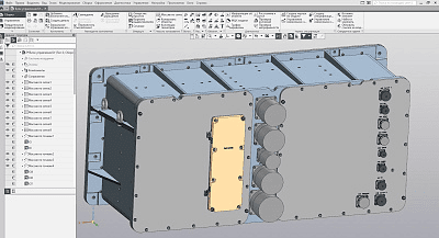
Available types of sheet construction:
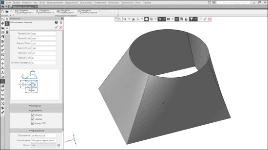
Cylindrical pipes: 5 types;Conical pipes: 5 types;Shaped pipes: rectangular, polygonal, flat-oval;The pipe is transitional;Composite bends: 2 types.
Equipment: Reamers

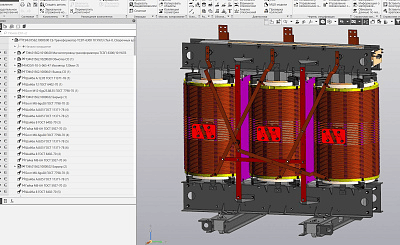
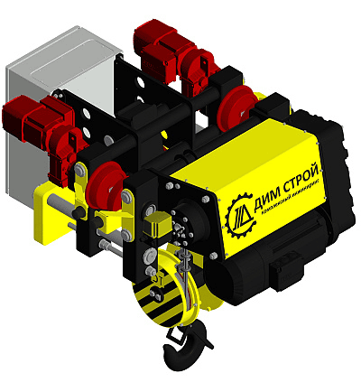
When drawing a drawing, various methods of dimensioning are available: "Between contour lines", "From construction line", "Table", "Do not measure curve".
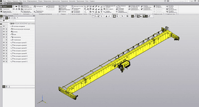
The flat pattern is generated in DXF format, which can be loaded into the nesting program, where the nesting map and CNC program are generated.
KOMPAS 3D Application
Mechanical
Four Exmples from Text Book will be given trainingOn software listed For the program Four problem will be given for self training with software to Trainee
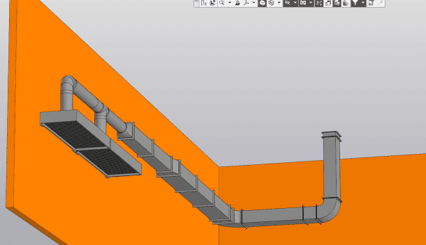
Equipment: Ventilation systems
The application allows you to:
to build air ducts in automatic mode with the arrangement of parts in the places of its rotations and branches, to perform corner sections;build models of air ducts according to ready-made trajectories;edit the geometry of ducts, its individual segments and elements.
Equipment: Ventilation systems

a set of parameters for a straight section of air ducts and elements of branches, turns, tees, etc.;orientation in space for turning rectangular air ducts;conditions for treating the ends of air ducts with flanges;the maximum length of straight sections of the air duct for their automatic division into segments;the composition of fasteners for connecting air ducts to each other and to other ventilation elements (the amount of required fasteners will be calculated automatically).
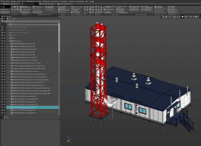
The set of air duct elements is formed on the basis of the nomenclature of the "Standard Products for COMPASS" application (requires a separately paid license).
Manufacturer: ASCON-Design SystemsLLC Requires for work: "KOMPAS-3D", "Materials and Assortments for KOMPAS", "Standard Products: Parts, Assemblies and Structural Elements for KOMPAS-3D"System requirements correspond to the system requirements of KOMPAS-3D
KOMPAS 3D Application
Mechanical
Features of the app
At industrial enterprises in Russia and the CIS countries, parts were repeatedly manufactured according to complex models, such as worm wheels of cylindrical and globoid worm gears, bevel gears with circular teeth. At the same time, each time they deserved high praise for the results of their industrial operation.
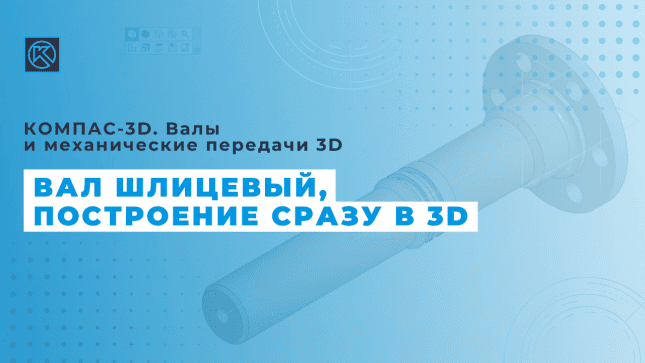
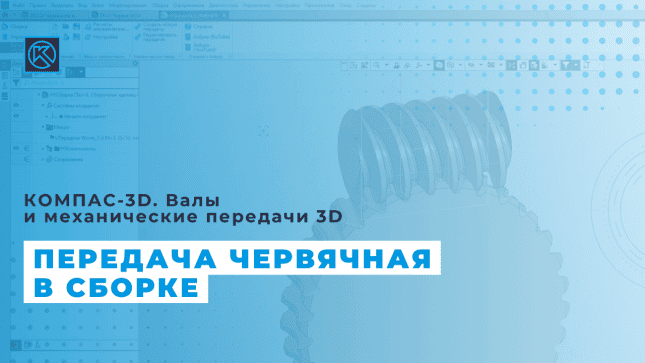
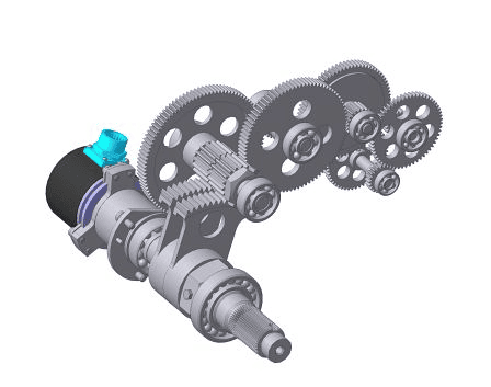
Four Exmples from Text Book will be given trainingOn software listed For the program Four problem will be given for self training with software to Trainee
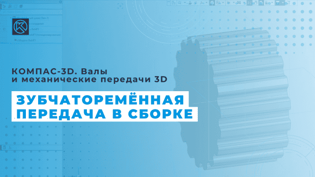
Shafts and 3D Mechanical Transmissions
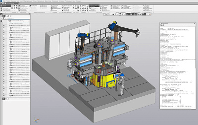
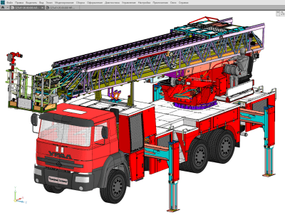
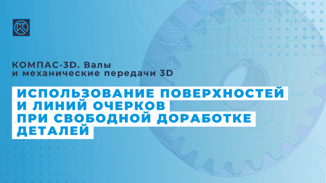
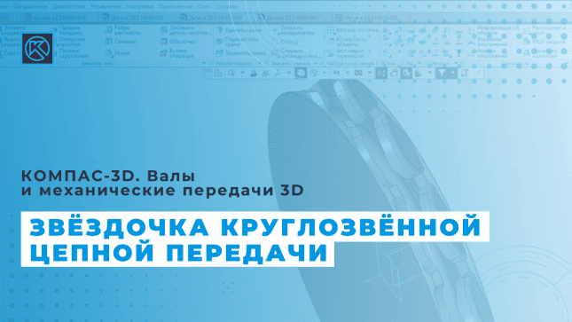
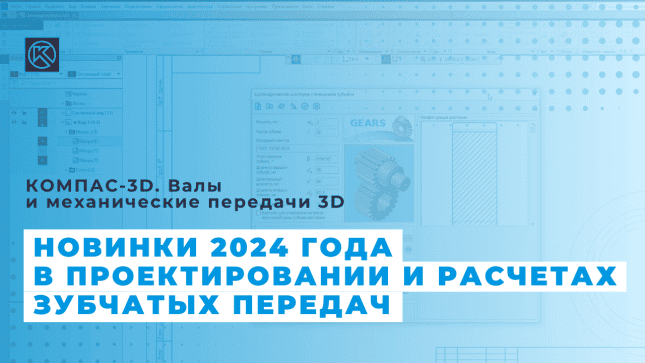
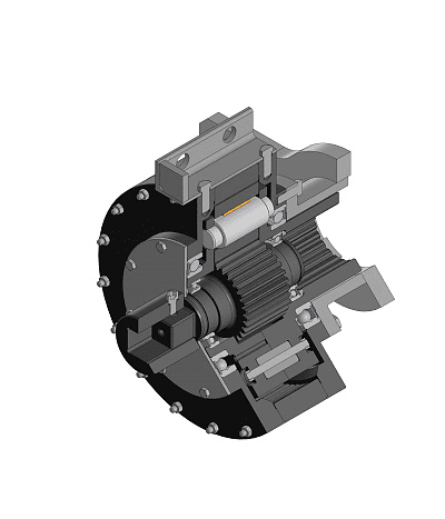
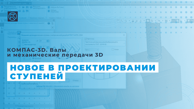
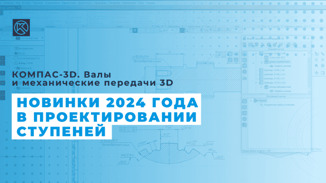
Thanks to the built-in modules: "KOMPAS-GEARS Mechanical Transmission Calculation Module" and "Material Selection Module", it is possible to perform geometric and strength calculations of mechanical transmissions, assign material for designed products, and fill the database with new materials. The results of calculations can be presented in the form of reports and saved in any convenient format. Standard KOMPAS-Graphic tools allow you to quickly draw up design documentation in accordance with the requirements of regulatory documents.
Shafts and 3D Mechanical Transmissions
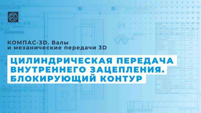
Cylindrical transmission of external meshing;Cylindrical internal gearing;James' planetary gear train with single-row satellites;helical involute gear;rack and pinion cylindrical gearing;Bevel gear with straight teeth;worm cylindrical gear;chain transmission with driven roller or bushing chain;V-belt transmission;flat-belt transmission;toothed blind coupling.
Geometric and design calculations, strength and durability gear calculations, and optimization calculations are available to users.
Manufacturer: ASCON-Design SystemsLLC Requires: KOMPAS-3DSystem requirements correspond to KOMPAS-3Dsystem requirements The add-on module is not available in KOMPAS-3D Home and KOMPAS-3D Educational version
a cylindrical gear with Novikov meshing;bevel gear with circular teeth;bevel transmission of internal meshing with straight teeth;hypoid transmission;orthogonal gear "Cylindrical worm – Helical helical wheel";worm globoid transmission;worm-rack and pinion transmissions;a toothed coupling;gear transmission;wallover transmission;flat-cylindrical transmission;cylindrical transmission of external meshing with arched teeth;Cylindrical transmission of external gearing (possibility of recovery calculation);chain transmission with gear drive chain;planetary pinion;External gear pump.
Another module, Clockwork, is designed for the design of time instruments. And the specialized module "Gear cutting tools" is designed for the design of gear cutting cutters and chisels
KOMPAS 3D Application
Mechanical
Four Exmples from Text Book will be given trainingOn software listed For the program Four problem will be given for self training with software to Trainee
Mechanics: Animation
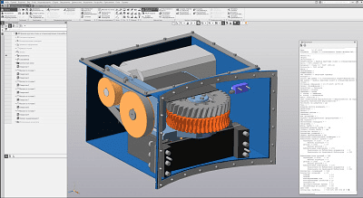
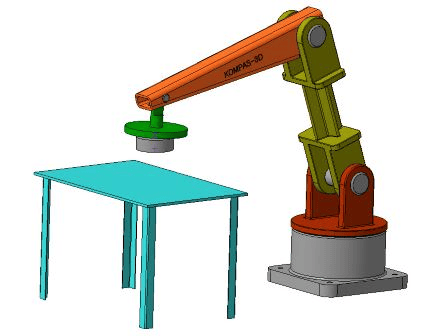
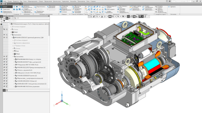
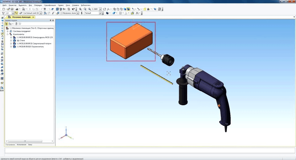
Imitation of the movements of various units and links of machines, devices, mechanisms and devices.Check for possible collisions of components during their movements to identify design errors.Create videos that show how the devices work for presentations or interactive technical tutorials.Creation of diagrams of successive positions of the mechanism — "kinograms" (a set of consecutive frames in the *.frw format — fragments of KOMPAS-Graphic).Recording motion videos in avi format. Playback parameters can be adjusted: set frame rate, pause between consecutive steps, cyclicality.
Mechanics: Animation
KOMPAS 3D Application
Mechanical
Four Exmples from Text Book will be given trainingOn software listed For the program Four problem will be given for self training with software to Trainee
APM FEM
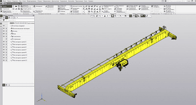
APM FEM
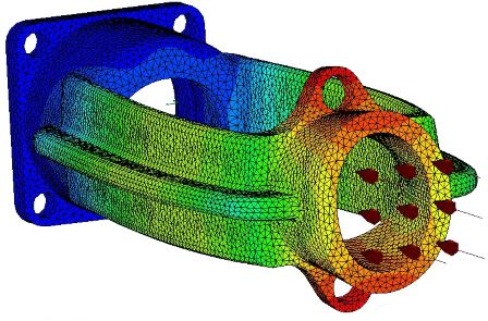
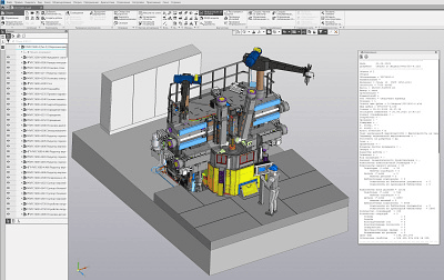
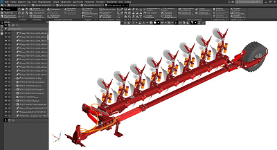
stress-strain state (static calculation);static strength of assemblies;sustainability;thermoelasticity;stationary thermal conductivity.
Dynamic analysis allows you to determine the frequencies and shapes of natural oscillations, including for preloaded models.
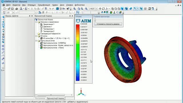
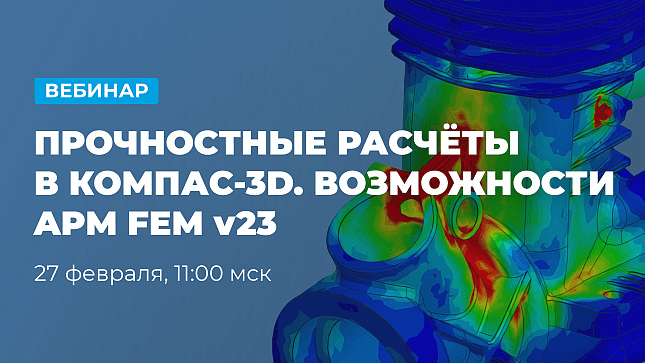
distribution of equivalent stresses and their components, as well as principal stresses;distribution of linear, angular and total displacements;Distribution of deformations across model elementsmaps of the distribution of internal efforts;the value of the safety factor and the form of the loss of stability;Distribution of safety factors and number of cycles according to the criterion of fatigue strength;distribution of safety coefficients according to the criteria of yield and strength;distribution of temperature fields and thermal stresses;center of gravity coordinates, weight, volume, length, surface area, moments of inertia of the model, as well as moments of inertia, static moments and cross-sectional areas;reactions in the supports of the structure, as well as the total reactions reduced to the center of gravity of the model.
KOMPAS 3D Application
Mechanical
Four Exmples from Text Book will be given trainingOn software listed For the program Four problem will be given for self training with software to Trainee
APM FEM. Topological optimization
stiffness,strength,mass.
An important optimization step is the selection of the design area in which the material can be located. To get the best result, you need to give a deliberately larger volume, taking into account design and technological limitations.
The sequence of actions corresponds to the usual static calculation in APM FEM. Loads, fixtures are set, and a finite element mesh is generated. The difference is in setting the parameters of the optimization problem.
APM FEM. Topological optimization
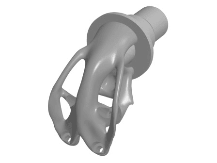
Generating responses is the selectable control values of the design that you are calculating. The following responses are available:
Volume of the part,total strain energy,weight,Moving a node or projecting itdisplacement of two nodes,tension of a group of elements.Selecting a target function for one of the responses, minimizing or maximizing it.Specify constraints as a lower or upper response bound.Setting Process Constraints:
maximum and minimum material thickness,symmetry of the detail,stamping,extrusion,3D printing.Formulation of the optimization problem. Select one of the target features and constraints for it.
A free form is the surface of a polyhedron rounded along the vertices and edges. A freeform is created from a polygon mesh, which can be modified, for example, by "dragging" vertices, faces, or edges and other actions.
For the resulting solid, it is necessary to perform a strength analysis again to make sure that the object is functional and meets the specified criteria.
APM FEM. Topological optimization
KOMPAS 3D Application
Mechanical
KOMPAS 3D Application
Mechanical
Four Exmples from Text Book will be given trainingOn software listed For the program Four problem will be given for self training with software to Trainee
Surface Smoothing Procedure (Freeform)
A free form is the surface of a polyhedron rounded along the vertices and edges. A freeform is created from a polygon mesh, which can be modified, for example, by "dragging" vertices, faces, or edges and other actions. Polygon mesh can be the result of 3D scanning or the result of topological optimization of the model.
Surface Smoothing Procedure (Freeform)
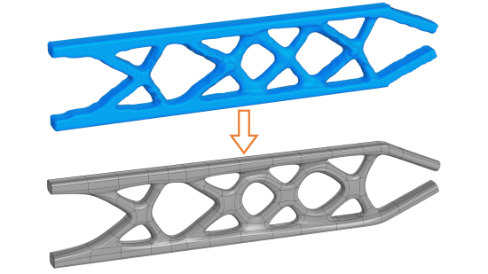
Model new freeform configurationsMove and align free-form objects.import polygonal objects (*.ply) and create free forms from them;save free shapes to polygon feature format (*.ply);Create polygon features and freeforms using an existing polygon model
KOMPAS 3D Application
Mechanical
KompasFlow
Four Exmples from Text Book will be given trainingOn software listed For the program Four problem will be given for self training with software to Trainee
KompasFlow
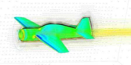
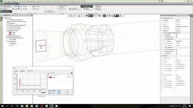
KompasFlow allows you to model:
KompasFlow
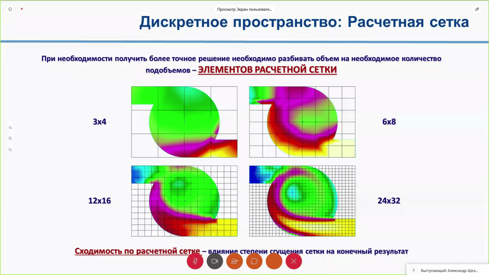
Flow of a single-component gas (supersonic and subsonic flow, compressible and incompressible media):
Calculation of the aerodynamic drag of the car, the lift of the wing;Flow in ventilation ducts and through ventilation grilles, calculation of losses;Air circulation in rooms, cabins;Calculation of wind load on structures and buildings.Fluid flow:
Calculation of hydrodynamic losses in pipes and shut-off valves;Calculation of hydraulic losses in liquid heat exchangers.Thermal Conductivity and Natural Convection given Radiative Heat Transfer:
Simulation of heat dissipation in heat exchangers;Simulation of ventilation, cooling and heating of rooms and cabins;Analysis of the cooling efficiency of electrical equipment.
KompasFlow supports parallel computing within a single multi-core processor.
KompasFlow
KOMPAS 3D Application
Mechanical
Four Exmples from Text Book will be given trainingOn software listed For the program Four problem will be given for self training with software to Trainee
IOSO-K Optimization
IOSO-K Optimization
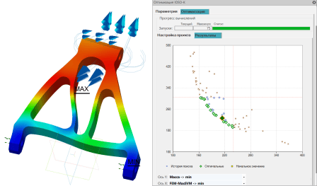
To answer this question, the IOSO-K Optimization app has been created.
Optimization is a targeted search for the best solutions. And IOSO is a multivariate nonlinear optimization technology developed by SIGMA Technology. The advantages of the technology include:
high speed of finding the optimal solution,simplicity (working with IOSO-K does not require special knowledge and settings).
Before you start optimizing, you need to ask yourself three questions:
What do I want to do with the part? Increase its strength, reduce weight, improve hydraulic performance, etc.?How do I want to achieve this? What do I need to change in the geometry (what parameters) to get the expected result?What limitations should I consider? For example, the minimum margin of safety.
IOSO-K Optimization
Among the optimized parameters may be:
any variables in KOMPAS-3D,KompasFlow boundary conditions.
Optimization can affect the following criteria:
mass and volume, surface area of the model,Stress and Displacement in APM FEM,calculation results in KompasFlow.
KOMPAS 3D Application
Mechanical
Four Exmples from Text Book will be given trainingOn software listed For the program Four problem will be given for self training with software to Trainee
Universal Express Movement
Universal Express Movement
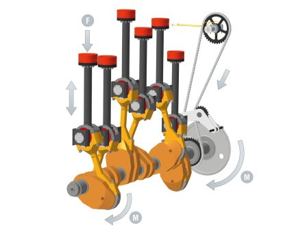
work with linear strength elements or changing according to a harmonic law, which are selected from a fixed database of models;setting a uniform, equally accelerated or equally decelerated motion, or changing it according to a harmonic law to solve kinematics problems;the possibility of solving contact interactions of bodies, the problem is solved under the condition that the bodies do not intersect during kinematic or dynamic motion.
Visualization of the library is created in a separate window, and the user is given the opportunity to receive visual information about the movement of the object and its dynamic and kinematic characteristics directly during the modeling process.
KOMPAS 3D Application
Mechanical
Four Exmples from Text Book will be given trainingOn software listed For the program Four problem will be given for self training with software to Trainee
KOMPAS-Expert
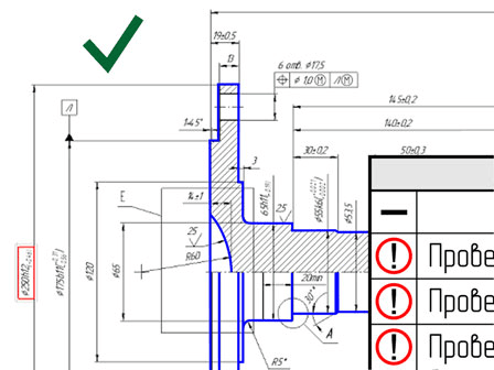
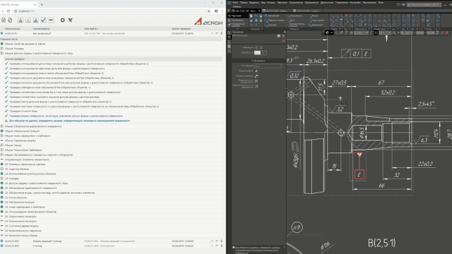
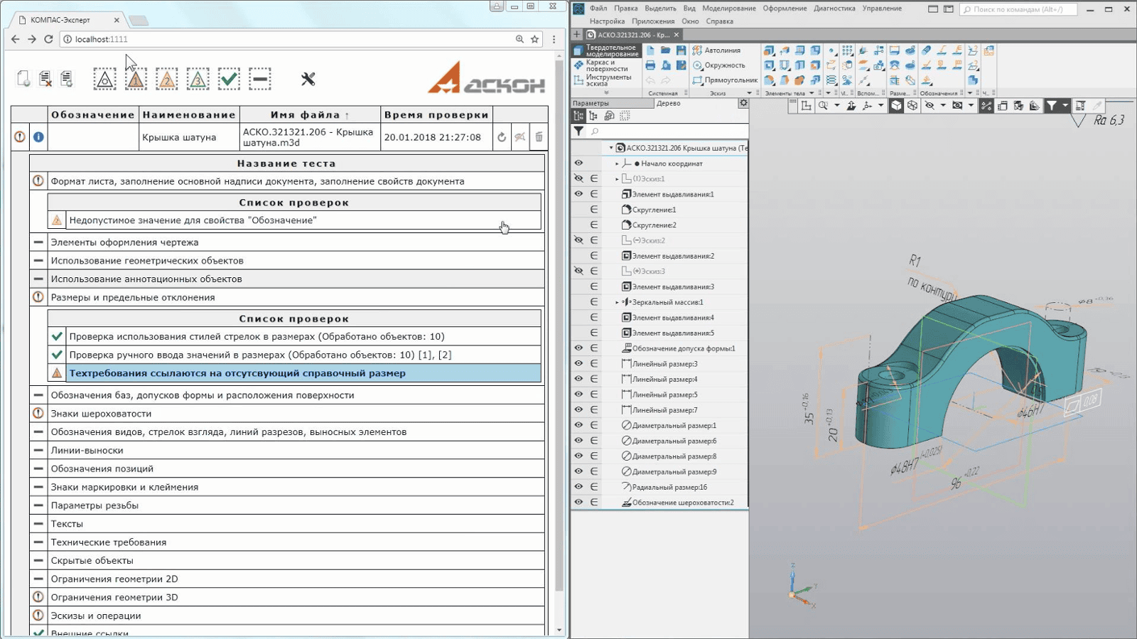
After launching the application, you need to select the documents to check. The result of the check is a list of errors, divided into groups and ranked by importance. The user can specify an error in the list, and the application will automatically open the checked document in COMPASS. The red box will highlight the location or object where the error was detected. If you agree with the assessment of KOMPAS-Expert, you can immediately correct it.
KOMPAS-Expert
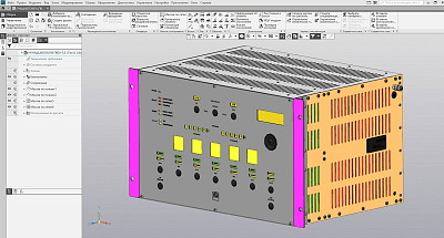
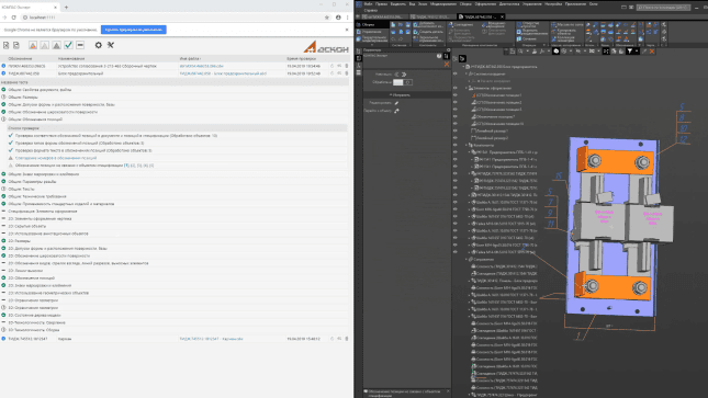
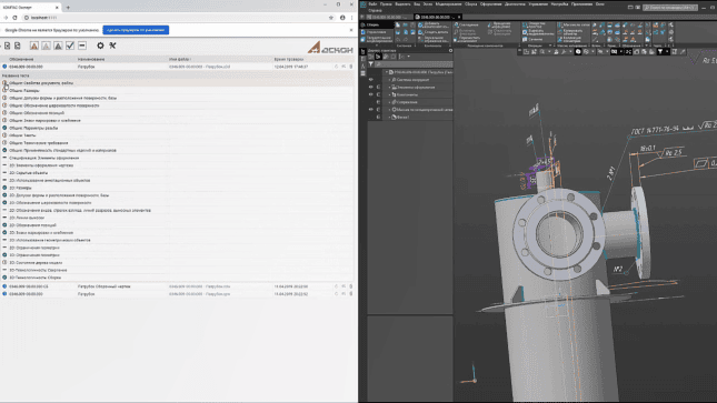
Standards for the design of the ESKD: the distance between dimension lines, the placement of text, the presence of intersections at the dimension line, line and serif styles, etc.;technological limitations of the enterprise: permitted values of roughness, quality, threads, position and shape of holes;rules for working in KOMPAS-3D: manual entry of dimensions, binding of the position designation to the specification, use of the axial object, and not lines with the axial style, etc.
You can customize any test by selecting correctness and significance criteria. Groups of tests can be combined into sets to test different types of documents
Manufacturer: ASCON-Design SystemsLLC Not available in KOMPAS-3D Home and KOMPAS-3D Educational version.Requires for work: "KOMPAS-3D"
KOMPAS 3D Application
Mechanical
Four Exmples from Text Book will be given trainingOn software listed For the program Four problem will be given for self training with software to Trainee
Coatings
There are two methods of coating:
Specifying the faces/solids to be covered.objects that are not covered.
KOMPAS-Expert
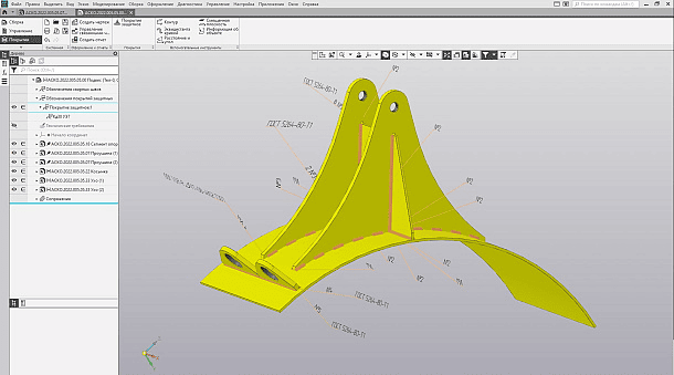
Coating materials are selected from the nomenclature of the application "Materials and Assortments for KOMPAS" (requires a separately paid license).
After specifying the thickness of the coating, its area and weight are calculated. This data is stored in the properties of the Coverage object and is available for transfer to other systems
KOMPAS 3D Application
Mechanical
Four Exmples from Text Book will be given trainingOn software listed For the program Four problem will be given for self training with software to Trainee
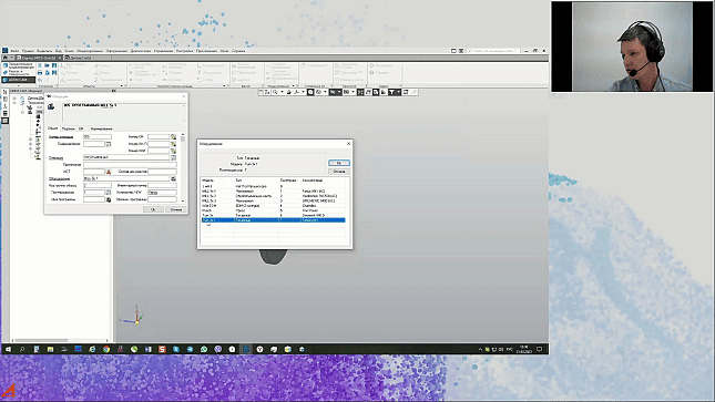
ADEM CAM for KOMPAS-3D
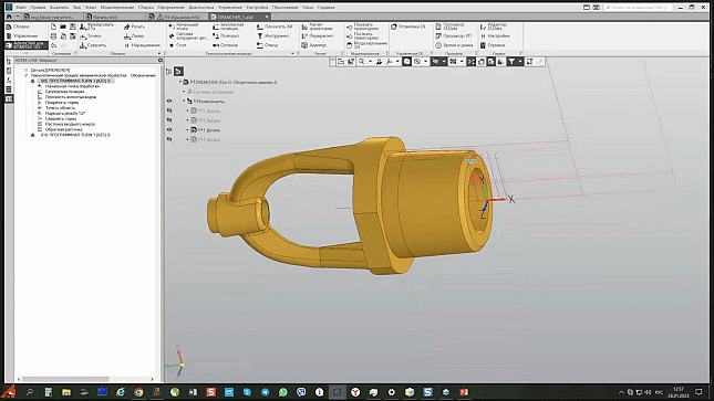
The application includes tools for the following types of processing:
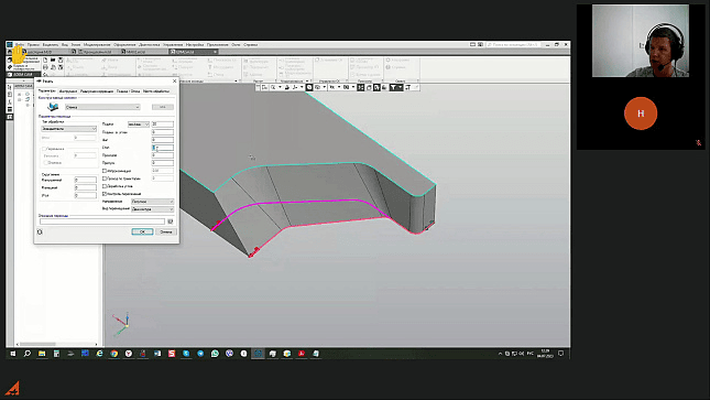
milling (2-5 axes);turning;turning and milling;multi-channel processing;erosion (2-4 axes);engraving (2-5 axes);contour cutting (2-5 axes);CNC machining;Additive processing.
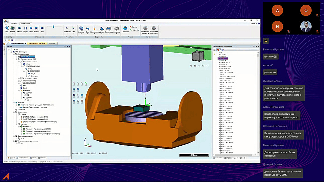
Technological objects that make up the technological process of processing are associatively connected with the geometric model, i.e. all changes made to the geometric model of the designed product are automatically reflected in the technological process of CNC machining.
ADEM CAM for KOMPAS-3D
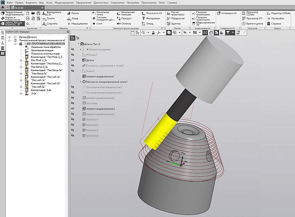
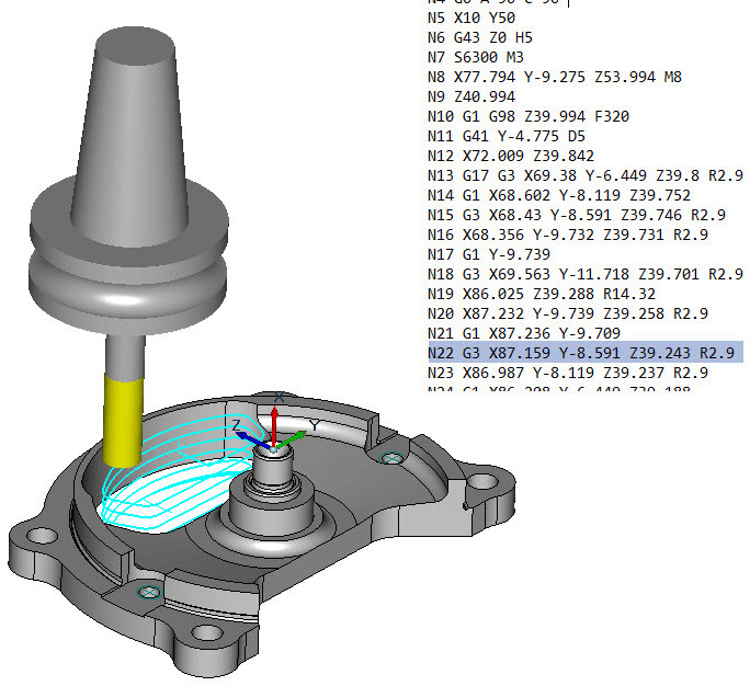
The application allows you to simulate the machining process with simulation of the tool movement along the calculated toolpath, to control the correctness and safety of the designed processing. If necessary, all information (geometry, equipment, equipment, control program, tool) can be transferred to an external verifier with a "single button". Machining simulation takes into account the features of the geometry of the part and tool.
Manufacturer: LLC "KRONA"Not available in KOMPAS-3D Home and KOMPAS-3D Educational version.Requires for work: "KOMPAS-3D"System requirements correspond to the system requirements of KOMPAS-3D
KOMPAS 3D Application
Mechanical
Four Exmples from Text Book will be given trainingOn software listed For the program Four problem will be given for self training with software to Trainee
CNC module. Turning
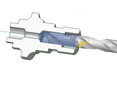
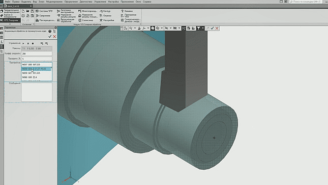
construction of processing contours by visual selection of surfaces or sketches directly on a three-dimensional model created in the KOMPAS-3D system;automatic calculation of trajectories. The resulting toolpaths are fully associative with the elements of the 3D model;generation of a control program in intermediate code based on the ISO standard;conversion of the control program into the codes of a specific CNC system using postprocessors. The basic delivery package includes postprocessors for the following systems: Mayak 600T, NC-31, FANUC Series MODEL D, SINUMERIK 802D, FAGOR CNC 8035T;visualization of processing in the window of the KOMPAS-3D system with simulation of material removal and control of the processing process.All operations are performed in the workspace of the KOMPAS-3D system using its interface elements (properties panel, tab in the construction tree, toolbar). "CNC Module. Turning" operates as part of the 32-bit and 64-bit versions of KOMPAS-3D.
CNC module. Turning
multi-pass — external turning, boring, undercutting, multi-pass groove;contour — contour turning (as a rule, finish);groove is a simple groove parallel to the coordinate axes;drilling – single- and multi-pass drilling, centering, machining of holes with axial tools;thread cutting with a cutter — multi-pass threading with a cutter (cylindrical, conical, end);thread cutting with a die/tap — threading with a die or tap;A segment is a segment, including a segment with a periodic output of the cutter
Use of parameterized models of tools and machine tools. The basic delivery set includes a set of ready-made three-dimensional models of tools and devices. At the same time, it is possible for the user to create his own models;Using the Python scripting programming language to edit and develop postprocessors.the ability to include CNC machine cycles in the control program.Manufacturer: National Research Ogarev Mordovia State University Not available in KOMPAS-3D Home and KOMPAS-3D Educational version.
KOMPAS 3D Application
Mechanical
Four Exmples from Text Book will be given trainingOn software listed For the program Four problem will be given for self training with software to Trainee
CNC module. Milling
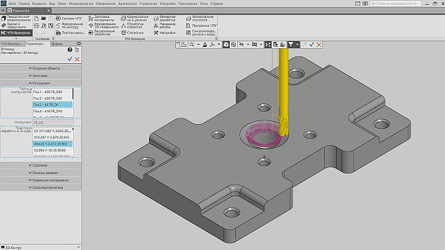
The initial geometric information for the creation of the control program is the design model of the part, created directly in the KOMPAS-3D system. This simplifies the work of the process engineer, who uses only one system without being distracted by third-party applications, and has complete confidence in the accuracy of the data on which the control program is based.
The application allows you to create a machining plan from the selection of a post-processor, workpiece, tool and fixtures to the generation of a control program in the CNC codes using a post-processor.
automatic calculation of milling toolpaths for 3-axis machining;generation of a control program in G-code based on the ISO standard;visualization of processing in the window of the KOMPAS-3D system;post-processing.
All operations are performed in the workspace of the KOMPAS-3D system using its interface elements. Machining elements are automatically recognized from the 3D model, which makes it easier to create a three-dimensional machining area. Elements such as pockets, through grooves, holes, chamfers are recognized. Automatic detection of residual material zones from previous treatments at Z-levels has been implemented. The residual material is determined in the corners or in areas of the machining area where the cutter has not passed the diameter. You can use model faces and edges, three-dimensional curves, and curves in a sketch as references. If you change the model, the application will also change the program for the CNC machine.
CNC module. Milling
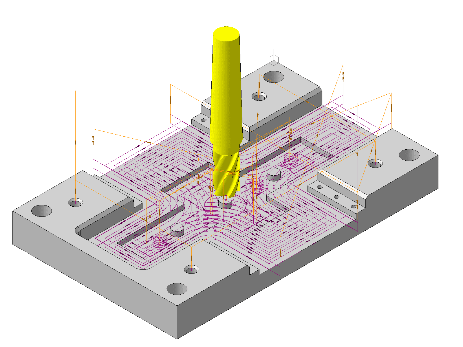
Z-Level Milling – Milling pockets and slots by dividing the machining area into horizontal levels. At each level, a processing trajectory is formed with the possibility of using three schemes: equidistant, zigzag, stitching.Z-Level Milling – Removes residual material after Z-level milling.Plane — milling of horizontal planes (a special case of milling at z-levels).Contour — processing along a three-dimensional contour. The strategy can also be used to select a hand-defined toolpath (e.g., sketched in a sketch or drawn with three-dimensional curves), including 3-axis machining.Hole machining is the machining of one or more holes, as well as round wells.Threading in holes.
Use of parameterized models of tools and machine tools, with the ability to create your own models;Using the Python scripting programming language to edit and develop postprocessors.the ability to include in the control program machine cycles of CNC systems, as well as subroutines for machining the same features.Manufacturer: National Research Ogarev Mordovia State University Not available in KOMPAS-3D Home and KOMPAS-3D Educational version.
KOMPAS 3D Application
Mechanical
Four Exmples from Text Book will be given trainingOn software listed For the program Four problem will be given for self training with software to Trainee
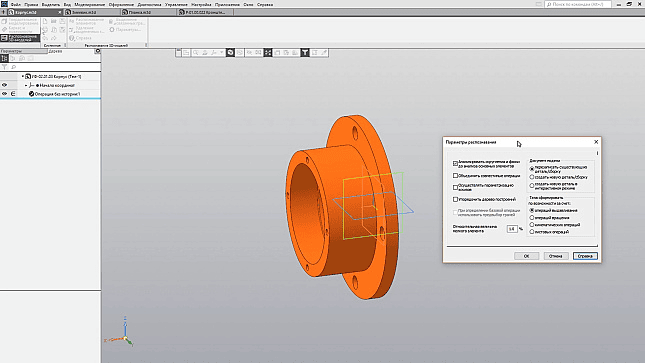
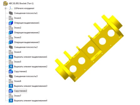
3D Model Recognition
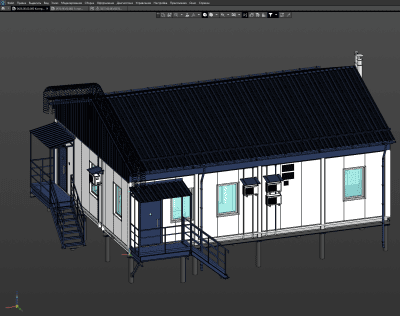
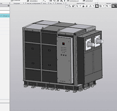
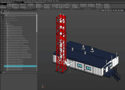
3D Model Recognition
KOMPAS 3D Application
Mechanical
Four Exmples from Text Book will be given trainingOn software listed For the program Four problem will be given for self training with software to Trainee
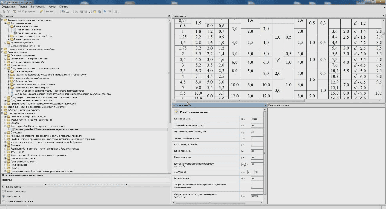
Electronic Constructor Handbook
Electronic Constructor Handbook
Electronic Constructor Handbook
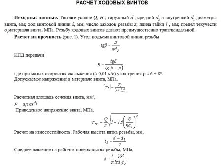
The results of the calculation are drawn up in the dialog box as a report and exported to Microsoft Word or OpenOffice.org Writer. The exported report is displayed as a table containing the names, designations, and values of variables (you can also create a report according to your own user template)