Industry Projects
Mechanical Projects Road Transport
Internship Program-Project Program-Product Dev, Program


UNIT I
Four Exmples from Text Book will be given trainingOn software listed For the program Four problem will be given for self training with software to Trainee
The company STC "APM" performed a strength calculation of the supporting elements of the frame of the auto-hydraulic lift (AGP).
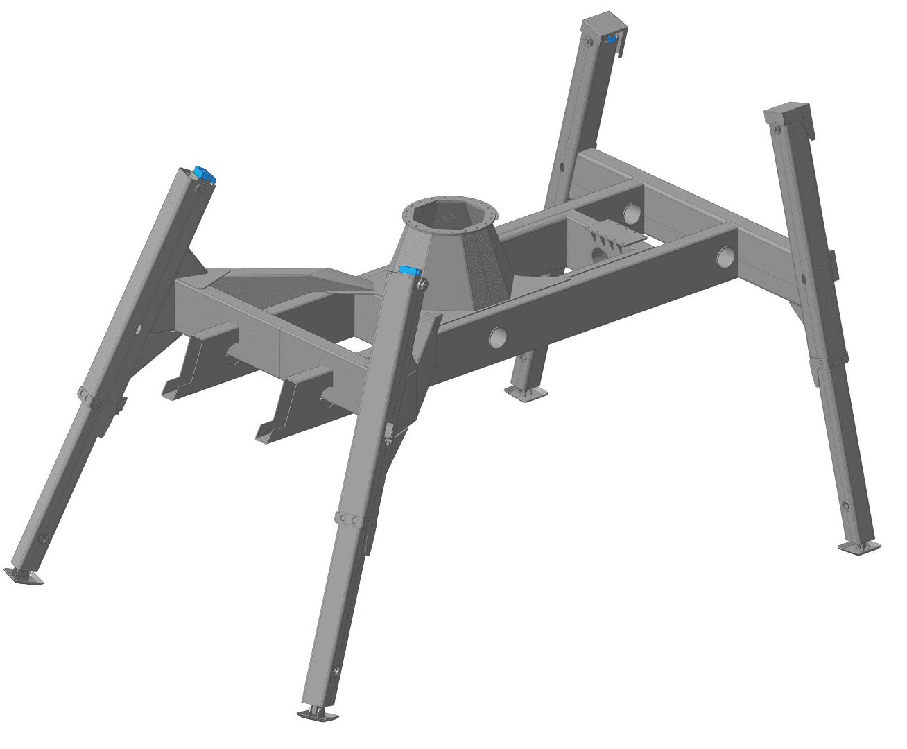
The frame of the auto-hydraulic lift is a metal welded structure with retractable support elements (outriggers). The outrigger reaches out using a hydraulic cylinder installed inside it. In transport condition, the outriggers are folded, and the frame of the car with the lift rests on the wheels. In working condition, the entire mass of the AGP rests on the ground through outriggers.
Geometric dimensions of the AGP frame: length 3935 mm, width 2838 mm, height 2240 mm. Frame weight: 1202 kg.
The calculation was carried out by order of NPO AVTOMASH LLC in the APM WinMachine software product.
UNIT IV
Four Exmples from Text Book will be given trainingOn software listed For the program Four problem will be given for self training with software to Trainee
The results of the static calculation showed that the stresses arising in the supporting elements of the AGP frame can locally (at the boundaries of the contact between the sliding plates and the outrigger body) exceed the yield strength of the material (09G2S steel). The most unfavorable for the supports are the angles of rotation of the boom over the front outriggers (from 90 to 270 degrees).
According to the technical specifications, the rear outrigger must withstand a load of 60% of the total weight of the auto-hydraulic lift in the position of the boom above it. According to the calculation, the stresses in the outrigger in this case do not exceed the yield strength of the material, therefore, strength is ensured.
According to the technical specifications, the front outrigger must withstand a load of 70% of the total weight of the auto-hydraulic lift in the position of the boom above it. According to the calculation, the stresses in the outrigger in this case locally exceed the yield strength of the material, but do not exceed the tensile strength. It can be argued that the strength of the outrigger is ensured, but plastic deformations of the metal are possible in the contact area of the sliding plate with the outrigger body.
The results of calculating the overall stability of outriggers showed that they have a significant margin. The minimum safety factor of outriggers is 7.
The work carried out showed the applicability of the APM WinMachine software package for solving


UNIT II
Four Exmples from Text Book will be given trainingOn software listed For the program Four problem will be given for self training with software to Trainee
Calculation model
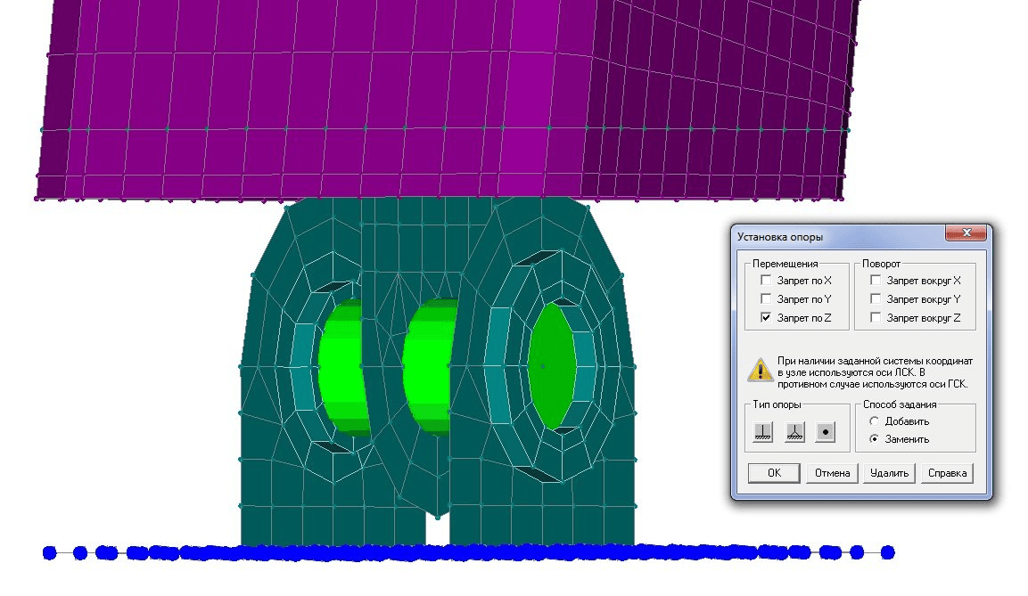
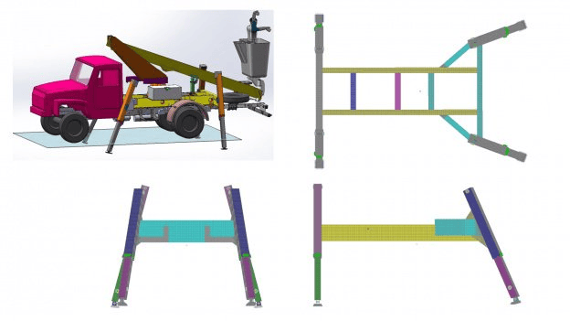
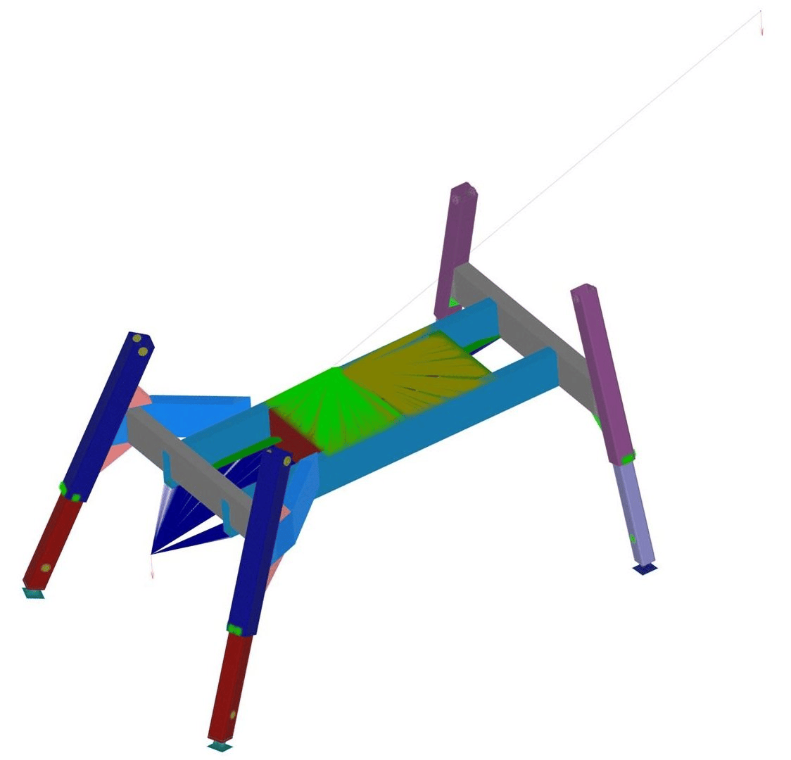
 The structure model was built in the APM Structure3D module. Some of the frame elements were not modeled, since the task is to calculate the strength of the outriggers, and not the entire frame. At the same time, the mass of missing elements will be taken into account in the future. All elements, except for hydraulic cylinders and axles, were modeled using plate finite elements. Hydraulic cylinders and axles were modeled by rod finite elements.
The frame rests on the ground through outriggers. Each outrigger has a hinged support leg at the bottom. The hinge allows the foot to rest on the ground with its entire area.
Design loads:
- Dead weight of the structure.
To account for the self-weight of a steel structure, the standard procedure for setting the "self-weight multiplier" in the Load Cases dialog box is used.  Weight of the chassis of the vehicle.
Consideration of the weight of the chassis is ensured by the vertical force applied at the center of gravity of the chassis.- Loads from the load carried on the frame.
This weight was modeled by a vertical force applied at the center of gravity of the load. - Load from boom with cradle.
This load on the frame is taken into account by the vertical force applied at the center of gravity of the boom.
UNIT III
Four Exmples from Text Book will be given trainingOn software listed For the program Four problem will be given for self training with software to Trainee
A static design of the structure in the working position for several boom positions was performed. Maps of the stressed and deformed state of the structure at the appropriate positions were obtained.
The overall stability of the structures has been checked. The calculation is carried out for the boom rotation angle of 138 degrees, at which the stresses in the front outrigger are maximum. As a result of the calculation, the lowest value of the safety factor of outriggers was obtained: Bush = 7. Thus, outrigger structures are stable under given loads.
The fatigue safety factor for the cases of boom position above the rear and front outriggers is determined.