Industry Projects
Construction Projects
Other Projects Canopy Structure
Internship Program-Project Program-Product Dev, Program



UNIT I
Four Exmples from Text Book will be given trainingOn software listed For the program Four problem will be given for self training with software to Trainee
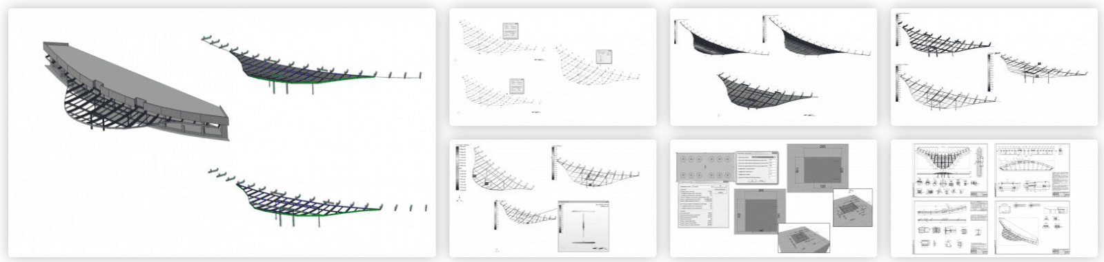
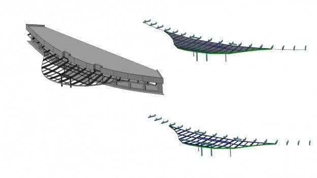
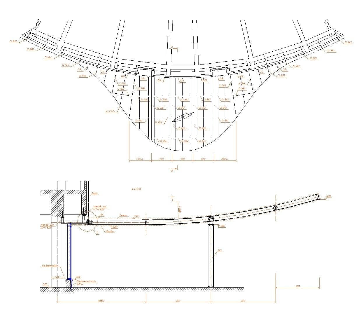
The structure of the canopy with a total area of 200 m2 consists of a metal frame.
The general structure of the canopy consists of cantilever I-beams, which are connected to each other using purlins made of bent channel.
The supporting columns in the central part of the canopy are made of I-section. Additional columns installed in the entrance group are made of a square pipe.
The sheathing of the canopy with the help of a corrugated sheet is carried out along the purlins so that the resulting package does not go beyond the boundaries of the I-beam. On top, there is an additional sheathing with two sheets of CBPB with a thickness followed by the laying of waterproofing and soft roofing.
The metal structure of the canopy is attached to the foundation in the columns and to the walls of the building.
The calculation was carried out in accordance with:
SP 20.13330.2011 Loads and Impacts. Updated edition of SNiP 2.01.07-85;SP 16.13330.2011 Steel structures. Updated edition of SNiP II-23-81.
UNIT IV
Four Exmples from Text Book will be given trainingOn software listed For the program Four problem will be given for self training with software to Trainee
The bolted connection calculation showed that all connections should be made on high-strength bolts of class 8.8 with a controlled screwing torque.
Summarizing the results obtained, it can be concluded that the canopy structure is able to bear the loads applied to it, corresponding to the construction area, and does not require additional measures to increase strength characteristics.
The work carried out showed the applicability of the APM Civil Engineering software package to solve complex construction problems.
UNIT II
Four Exmples from Text Book will be given trainingOn software listed For the program Four problem will be given for self training with software to Trainee
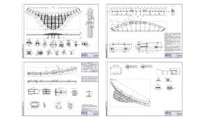
As part of the work of the design team, a set of documentation was issued, including a calculation and explanatory note and an album of drawings of the KM/KMD brand.
The calculation and explanatory note includes:
description of the design scheme (model, connections, materials);loading of the structure (own weight, snow loads);calculation and analysis of results (analysis of stresses, displacements);verification of non-dry ability according to SP 16.13330.2011 Steel structures;calculation of bolted connections;calculation and selection of anchor bolts.
The KM/KMD drawing album includes:
a list of shipping stamps;selection of hardware;steel sampling;anchoring plans;wiring diagrams and assemblies;detail drawings of all shipping marks.
UNIT III
Four Exmples from Text Book will be given trainingOn software listed For the program Four problem will be given for self training with software to Trainee
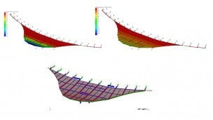
A static analysis of the structure for the main combination of loads, stability calculation, calculation of the bearing capacity of the canopy columns, as well as the calculation of bolted connections of structural elements were carried out.
Analysis of the results of the static calculation shows that at the specified design loads, the equivalent stresses arising in the elements of the canopy structure when using the specified sections do not exceed the yield strength of the materials used, i.e. the required strength is provided.
The maximum vertical deflections of the structure exceed the permissible limit. Vertical deflections do not affect the performance of the structure and do not worsen the appearance of structures, in connection with which the customer decided to neglect these deflections.