Industry Projects
Mechanical Projects Aviation
Pilot Seat
Internship Program-Project Program-Product Dev, Program

APM WINMACHINE APM CIVIL APM FEM

UNIT I
Four Exmples from Text Book will be given trainingOn software listed For the program Four problem will be given for self training with software to Trainee
Pilot's seat
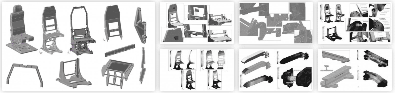
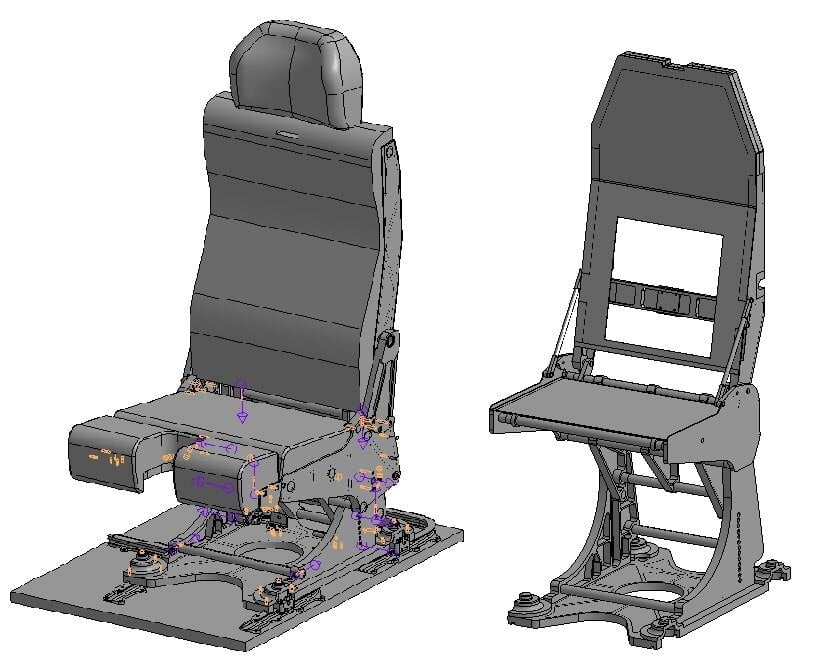
STC APM LLC carried out verification calculations of the strength and stiffness of the load-bearing (load-bearing) elements in the structure of the pilot's seat under static and dynamic loads.
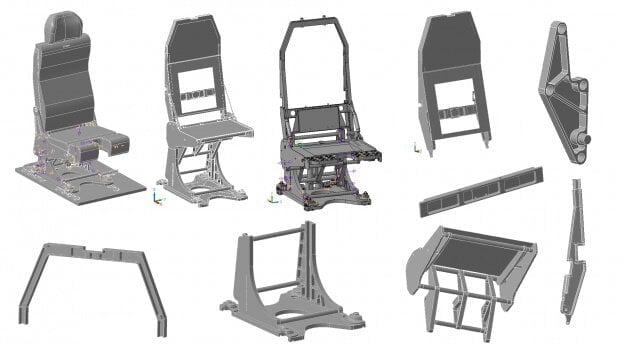
The main components of the chair:
Backrest;Seat;Vertical movement mechanism;Carriage;Foundation;Power elements.
Verification calculations were carried out using the software product - "CAD\CAE system for computer-aided calculation and design of machine parts, mechanisms, structural elements and assemblies, machine-building objects and equipment APM WinMachine".
STC APM LLC carried out verification calculations of the strength and stiffness of the load-bearing (load-bearing) elements in the structure of the pilot's seat under static and dynamic loads.
The main components of the chair:
Backrest;Seat;Vertical movement mechanism;Carriage;Foundation;Power elements.
Verification calculations were carried out using the software product - "CAD\CAE system for computer-aided calculation and design of machine parts, mechanisms, structural elements and assemblies, machine-building objects and equipment APM WinMachine".
UNIT IV
Four Exmples from Text Book will be given trainingOn software listed For the program Four problem will be given for self training with software to Trainee
Results of the completed project
Analyzing the presented results for all calculated variants of load cases of the modified model, the following conclusions can be drawn.
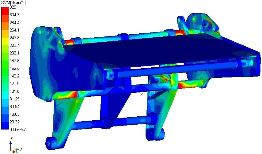
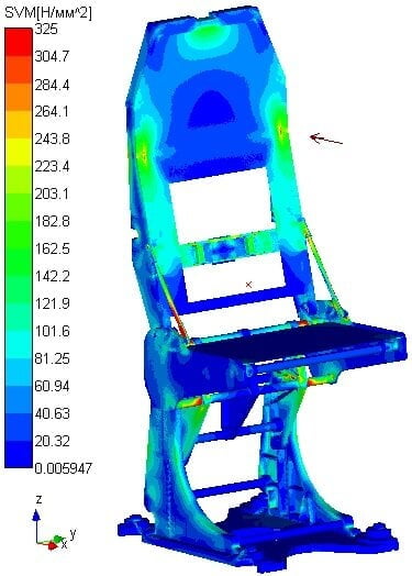
The main part of the load-bearing metal structures of the pilot's seat when loaded with the considered combinations of design static loads experiences stresses that do not exceed the permissible ones, and, therefore, the main part of the seat structure operates in the zone of elastic deformations. The maximum equivalent stresses estimated by the Guber-Mises strength hypothesis (strength theory 4), which exceed the yield strength of the aluminum alloy, occur under the action of a number of combinations of loads in the following areas of the load-bearing elements of the chair structure:
in the seat base plate;in the clutch, in the place of attachment to the sidewall of the seat;in the side of the seat at the place of attachment to the clutch;in the seat tubes (upper and lower) in the places of attachment to the side brackets of the chair;on the edges of the side brackets of the chair.
In some of these areas, namely the top tube of the seat and the side brackets of the chair, the equivalent stresses exceeded the tensile strength of the aluminum alloy.
When loading with the considered combinations of dynamic loads, the result obtained at the maximum value of the criterion (stresses) corresponding to the peak of the load impulse was evaluated; At the same time, the tensile strength of materials is exceeded in the following areas of the load-bearing elements of the structure:
Analyzing the presented results for all calculated variants of load cases of the modified model, the following conclusions can be drawn.
The main part of the load-bearing metal structures of the pilot's seat when loaded with the considered combinations of design static loads experiences stresses that do not exceed the permissible ones, and, therefore, the main part of the seat structure operates in the zone of elastic deformations. The maximum equivalent stresses estimated by the Guber-Mises strength hypothesis (strength theory 4), which exceed the yield strength of the aluminum alloy, occur under the action of a number of combinations of loads in the following areas of the load-bearing elements of the chair structure:
in the seat base plate;in the clutch, in the place of attachment to the sidewall of the seat;in the side of the seat at the place of attachment to the clutch;in the seat tubes (upper and lower) in the places of attachment to the side brackets of the chair;on the edges of the side brackets of the chair.
In some of these areas, namely the top tube of the seat and the side brackets of the chair, the equivalent stresses exceeded the tensile strength of the aluminum alloy.
When loading with the considered combinations of dynamic loads, the result obtained at the maximum value of the criterion (stresses) corresponding to the peak of the load impulse was evaluated; At the same time, the tensile strength of materials is exceeded in the following areas of the load-bearing elements of the structure:

UNIT II
Four Exmples from Text Book will be given trainingOn software listed For the program Four problem will be given for self training with software to Trainee
During operation, the chair is subject to the following loads (overloads):
1. Static (overloads in directions relative to the direction of seat installation (in flight))
forward - 9g;sideways - 4g;up - 3g;down - 6g;back - 1.5g.
2. Dynamic
forward - 16g - peak (deviation of 10 degrees from the direction of flight);down - 14g - peak (deviation of 30 degrees from the perpendicular to the floor of the aircraft).
Under static loading, the resulting maximum equivalent stresses in the structure should not exceed the yield strength of the material, i.e. all load-bearing elements of the structure should operate in an elastic deformation zone and at the same time plastic (residual) deformations should not occur after the load is removed.
Under dynamic loading, the resulting maximum equivalent stresses in the structure should not exceed the tensile strength of the material, i.e. there is no destruction of materials and the main load-bearing structure remains intact.
1. Static (overloads in directions relative to the direction of seat installation (in flight))
forward - 9g;sideways - 4g;up - 3g;down - 6g;back - 1.5g.
2. Dynamic
forward - 16g - peak (deviation of 10 degrees from the direction of flight);down - 14g - peak (deviation of 30 degrees from the perpendicular to the floor of the aircraft).
Under static loading, the resulting maximum equivalent stresses in the structure should not exceed the yield strength of the material, i.e. all load-bearing elements of the structure should operate in an elastic deformation zone and at the same time plastic (residual) deformations should not occur after the load is removed.
Under dynamic loading, the resulting maximum equivalent stresses in the structure should not exceed the tensile strength of the material, i.e. there is no destruction of materials and the main load-bearing structure remains intact.
UNIT III
Four Exmples from Text Book will be given trainingOn software listed For the program Four problem will be given for self training with software to Trainee
Calculation model
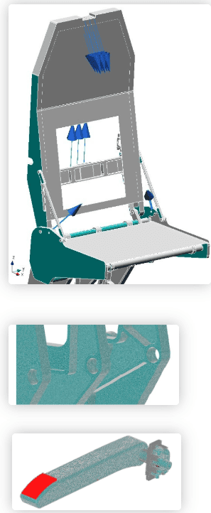
Finite element models of the chair structure are created on the basis of 3D models made in KOMPAS 3D and submitted by the customer, in accordance with the terms of reference.
The geometry of the 3D computational model is slightly different from the original one. This is due to the need for the correct creation of a mathematical model, in particular, taking into account only the load-bearing (load-bearing) elements of the chair structure in the model, as well as the formation of a finite element grid from solid-elements.
The model takes into account:
loads from seat belts on the load-bearing elements of the seat;loads from overload.
For dynamic calculations, a pulse was formed to simulate the increase and removal of loads.
Calculation results
Static and dynamic stress-strain state of the load-bearing elements of the chair structure was carried out in geometrically and physically linear positioning using the finite element method in the APM Structure3D and APM Studio modules, which are part of the computer-aided calculation and design system for machine parts, mechanisms, structural elements and assemblies, machine-building facilities and APM WinMachine equipment.
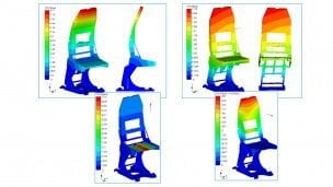
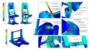
As a result of the calculation, color maps of the results of the stress-strain state analysis for various combinations of load cases are obtained.
Strength and fatigue calculations of the armrest were carried out. The purpose of this calculation was to analyze the stress-strain state of the armrest structure loaded with static and cyclic vertical distributed load, as well as to assess the fatigue life of the product under the action of cyclic load.
Rail calculation was performed. The purpose of this calculation was to analyze the stress-strain state of the rail structure loaded with a static distributed load (instantaneously acting dynamic load) applied vertically up along the edges of the T-flanges.
Calculations of the bolted connection of the upper seat belt coil fastening were also carried out and the analysis of the fastening of the seat base to the rail was performed.
Finite element models of the chair structure are created on the basis of 3D models made in KOMPAS 3D and submitted by the customer, in accordance with the terms of reference.
The geometry of the 3D computational model is slightly different from the original one. This is due to the need for the correct creation of a mathematical model, in particular, taking into account only the load-bearing (load-bearing) elements of the chair structure in the model, as well as the formation of a finite element grid from solid-elements.
The model takes into account:
loads from seat belts on the load-bearing elements of the seat;loads from overload.
For dynamic calculations, a pulse was formed to simulate the increase and removal of loads.
Calculation results
Static and dynamic stress-strain state of the load-bearing elements of the chair structure was carried out in geometrically and physically linear positioning using the finite element method in the APM Structure3D and APM Studio modules, which are part of the computer-aided calculation and design system for machine parts, mechanisms, structural elements and assemblies, machine-building facilities and APM WinMachine equipment.
As a result of the calculation, color maps of the results of the stress-strain state analysis for various combinations of load cases are obtained.
Strength and fatigue calculations of the armrest were carried out. The purpose of this calculation was to analyze the stress-strain state of the armrest structure loaded with static and cyclic vertical distributed load, as well as to assess the fatigue life of the product under the action of cyclic load.
Rail calculation was performed. The purpose of this calculation was to analyze the stress-strain state of the rail structure loaded with a static distributed load (instantaneously acting dynamic load) applied vertically up along the edges of the T-flanges.
Calculations of the bolted connection of the upper seat belt coil fastening were also carried out and the analysis of the fastening of the seat base to the rail was performed.