Industry Projects
Construction Projects
Shelves Structure Mezzanien Rack
Internship Program-Project Program-Product Dev, Program



UNIT I
Four Exmples from Text Book will be given trainingOn software listed For the program Four problem will be given for self training with software to Trainee
Rack with mezzanine
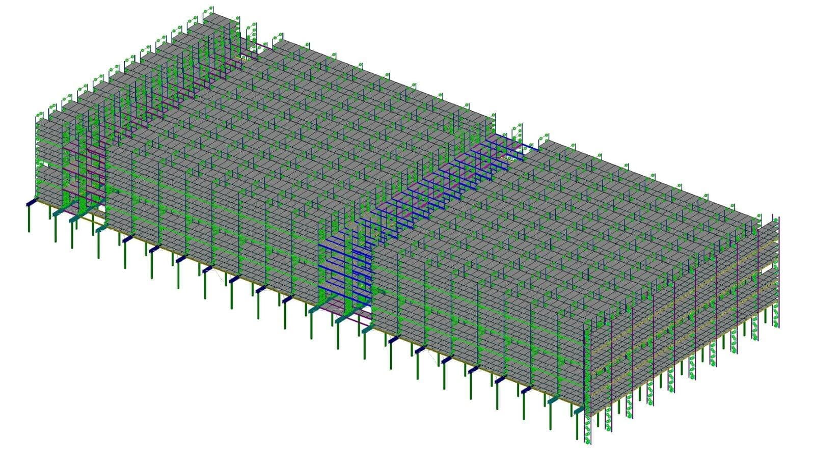
The metal structure of the rack with a mezzanine is located inside the building of the warehouse complex.
Geometric dimensions of the structure: length 67,164 mm, width 53,306 mm, height 12,008 mm.
A rack is a multi-level spatial structure designed for storing goods. The rack structure rests on columns. The support columns are connected by braces and beams made of sigma profile, forming a platform for the installation of vertical frames made of Ω-shaped perforated profile (minirack) posts. Each pair of posts is connected by diagonal braces. The beams for installing pallets on them are fixed on the racks.
Also, on the side of the main structure of the rack with a mezzanine, additional sections of the rack are installed, formed by racks of a ω-shaped perforated profile. The posts are connected with braces.
The calculation was carried out in accordance with the current regulatory documents:
- GOST 28766-90 Racks. Calculation basics.
- SP 16.13330.2011 Steel structures. Updated edition of SNiP II-23-81.
- SP 20.13330.2011 Loads and Impacts. Updated edition of SNiP 2.01.07-85.
The calculation was carried out in the APM CivilEngineering software product.
The calculation was carried out by order of Kifato MK LLC.
UNIT IV
Four Exmples from Text Book will be given trainingOn software listed For the program Four problem will be given for self training with software to Trainee
Analysis of the results of the static calculation shows that at the specified design loads, the equivalent stresses arising in the frame structural elements when using the specified sections do not exceed the yield strength of the materials used, i.e. the required strength is provided. In the most unfavorable case of loading, the safety coefficient for the design resistance, for a reinforced structure, is greater than one and is equal to 1.01.
The maximum total movements of the transom are 11.03 mm and do not exceed the permissible limit. Therefore, the necessary rigidity of the structure is ensured.
The structure does not need additional measures to increase its stability. The minimum safety factor of this rack design is 8.9.
Checking the load-bearing capacity of the most loaded structural elements showed that all the coefficients of working conditions have values less than one, which is acceptable and indicates the acceptable operation of the elements. Thus, it can be concluded that the bearing capacity of these structural elements is ensured.
Summarizing the results obtained, it can be concluded that the rack structure is capable of bearing the loads applied to it, and does not require additional measures to increase the strength characteristics (except for the above).
The considered project complies with Russian standards (GOST 28766-90, SP 16.13330.2011, SP 20.13330.2011). This is evidenced by the conclusions made above.
The work carried out showed the applicability of the APM Civil Engineering software package for solving complex problems of strength analysis of rack structures.
UNIT II
Four Exmples from Text Book will be given trainingOn software listed For the program Four problem will be given for self training with software to Trainee
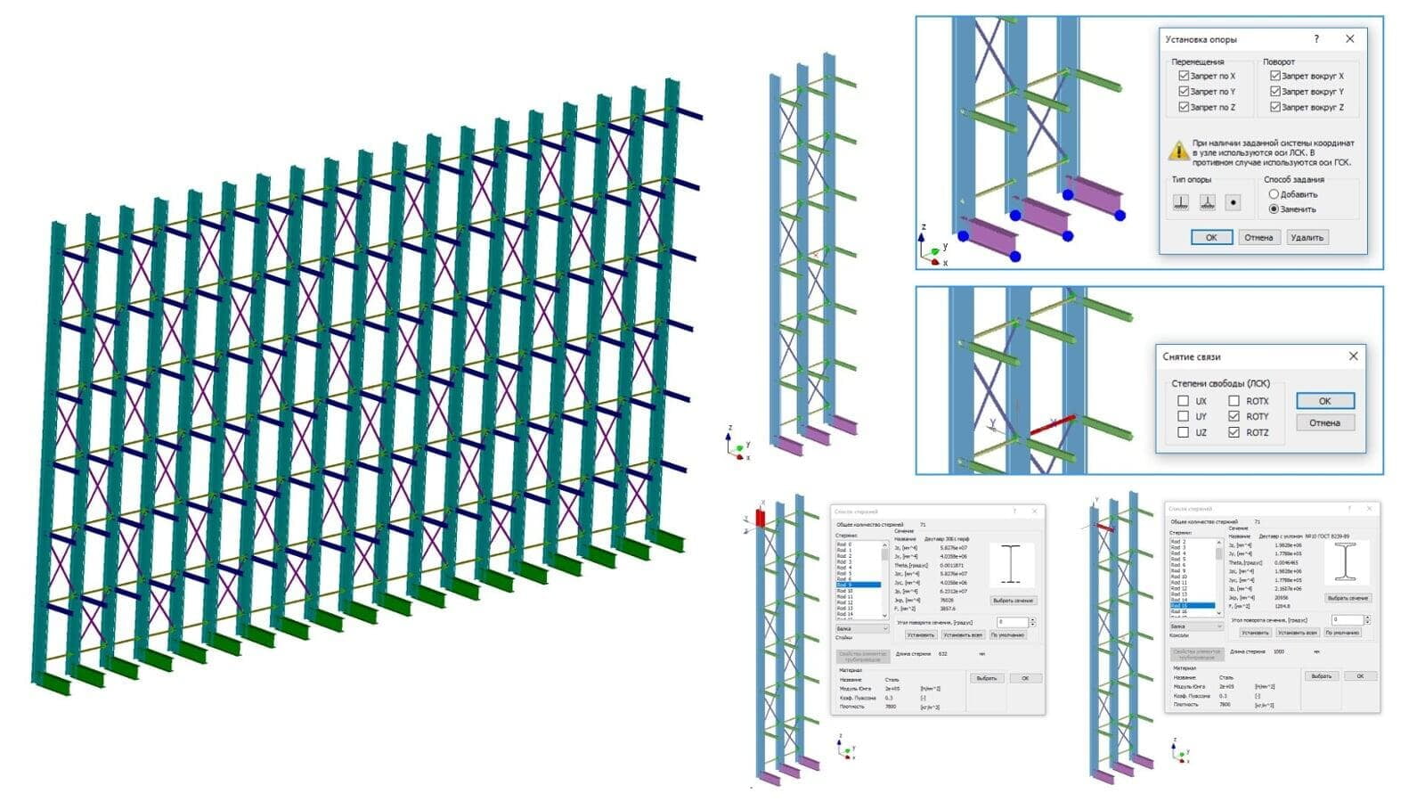
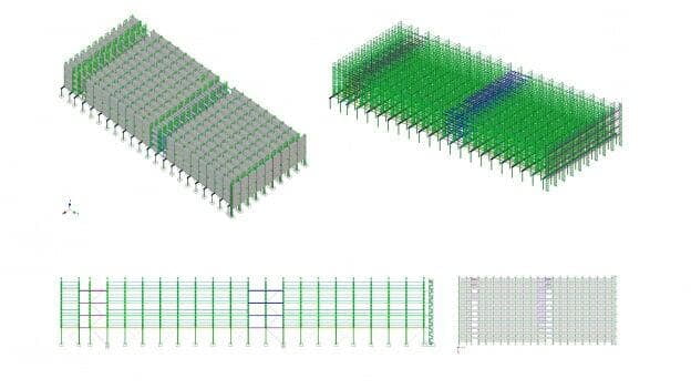
The design scheme of the rack structure is built on the basis of drawings submitted by the customer.
The elements of the load-bearing metal structure of the rack were modeled using rod finite elements.
Since the structure of the rack is larger, we will limit ourselves to calculating only a fragment of the structure.
In connection with the perforation of the bearing racks, the calculation will be carried out taking into account the reduced profile in accordance with clause 9.2.3 EN 15512 Steel static storage systems - Adjustable pallet racking systems - Principles for structural design.
The connections in the rack model are central, i.e. the connection is carried out through the centers of gravity of the sections of the corresponding elements.
The model has both rigid connections and hinged ones with one rotational degree of freedom. In the design of the rack, the rigidity of the connection must be ensured by tightening the bolted connection.
The metal structure of the rack is rigidly fastened with anchors to the concrete floor. The restrictions introduced in this case are as follows: prohibition of all movements and turns.
To take into account the dead weight of a metal structure, the standard procedure for setting the "self-weight multiplier" is used.
To take into account the load from the weight on one shelf of the rack, the "Load on the shelves" load was organized.
The load on the mezzanine deck is included in the load load on the mezzanine deck.
The load on the staircase is taken into account in the load load "Load on the staircase".
UNIT III
Four Exmples from Text Book will be given trainingOn software listed For the program Four problem will be given for self training with software to Trainee
The static analysis was carried out in the module for the calculation of the stress-strain state, stability, using the finite element method - APM Structure3D.
Maps of the stressed and deformed state of the structure under the corresponding loading options are obtained.
The maximum deflections of the structure were estimated in accordance with the requirements of GOST 28766-90.
The overall stability of the structure was also checked in accordance with SP 16.13330.2011.
According to SNiP II-23-81* "Steel Structures", the bearing capacity of the most loaded structural elements was checked.
In order to reduce the load on the metal structure, some changes were made to the design of the rack.