Physics
Overview of physics
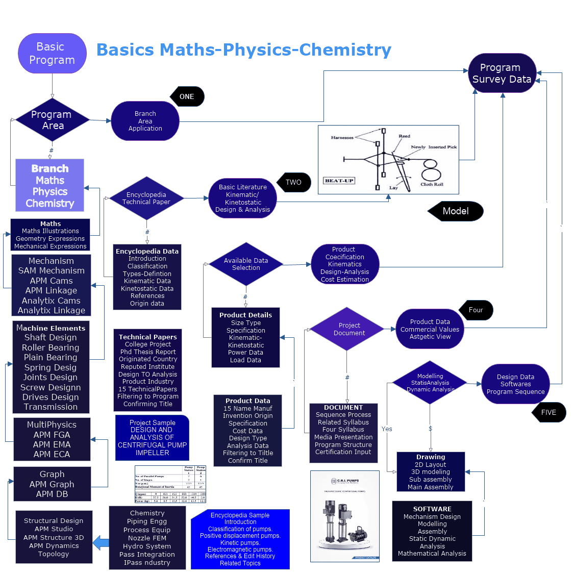
Women Graduates are trained with basics in Industry application from basic science Mathematics, Physics, Chemistry
Training in application Software by Industry Professional, to train others with preparation as TRAINER to empower.
Empowering areas are ACADEMIC SERVICE-ENTREPRENEURSHIP-DESIGN SERVICE-INDUSTRIES-SOCIAL ENGINEERING
SAM 8.5 - by Artas Engineering Software
Design, motion/force analysis and constrained optimization of linkage mechanisms and drive systems.
UNIT I
Four Exmples from Text Book will be given trainingOn software listed For the program
Four problem will be given for self training with software to Trainee
General
- planar mechanisms
- design, simulation and optimization
- CAD-interface, DXF import/expor
- planar mechanisms
- design, simulation and optimization
- CAD-interface, DXF import/expor
UNIT II
Four Exmples from Text Book will be given trainingOn software listed For the program
Four problem will be given for self training with software to Trainee
Modelling
- beam, slider, spring
- belt, gear, rack-and-pinion
- non-linear spring, curved slider
UNIT III
Four Exmples from Text Book will be given trainingOn software listed For the program
Four problem will be given for self training with software to Trainee
Input Motion
- composition of standard profiles
- textfile
- multiple actuators
- Analysis Results
- positions, angle and lengths
- velocity, acceleration, force and torque
- user expressions
UNIT IV
Four Exmples from Text Book will be given trainingOn software listed For the program
Four problem will be given for self training with software to Trainee
Design wizards
- angle-function generation
- 4-bar mechanisms
- exact linear guiding
Optimization
- all geometry
- multiple parameters
- function or path
Duration 30 Hours
Teachers
Clear illustration of your lessons
Design engineers
The tool you can rely on!
Specialists
Increase your solution space in no time!
APM WinMachine
Cam Analysis and Design Module

APM Cam
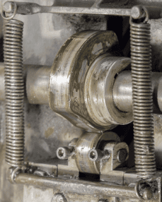
Cam mechanisms are used to convert rotational motion into translational or rocking motion of the pushrod. In mechanisms of this type, the law of motion of the pushrod is determined by the geometric shape of the cam and the type of pushrod. Cam mechanisms are often used as control devices that set a particular law of motion. The APM Cam module is designed to design cam mechanism elements according to the known law of motion.
UNIT I
Four Exmples from Text Book will be given trainingOn software listed For the program
Four problem will be given for self training with software to Trainee
Preparation of initial data
The preparation of initial data comes down to the selection of the type of cam mechanism, the setting of some auxiliary parameters, including geometric, as well as information on materials and the type of the law of motion.
The law of motion can be specified in one of the following ways:
- relocation schedule;
- a graph that determines the change in speed by the angle of rotation of the cam;
- A graph that determines the change in acceleration by the angle of rotation of the cam.
UNIT II
Four Exmples from Text Book will be given trainingOn software listed For the program
Four problem will be given for self training with software to Trainee
For entering graphical information, the module has a special tool with which you can set the graph of the function in the form of a spline or in the form of a set of linear segments and any combination of them. The motion function defined in this way can be edited if necessary.
It is possible to enter analytical functions and information from a file. For analytical function definition, there is an analytical expression processing editor.
UNIT III
Four Exmples from Text Book will be given trainingOn software listed For the program
Four problem will be given for self training with software to Trainee
Calculation criteria
The cam profile is selected based on the specified law of motion of the pushrod, the diameter is selected from the pressure angle limitation, and the thickness and radius of the pushrod are selected from the constraints on the highest stresses in the contact.
UNIT IV
Four Exmples from Text Book will be given trainingOn software listed For the program
Four problem will be given for self training with software to Trainee
Calculation results
The ARM Cam module allows you to:
- calculate the cam profile and represent it in Cartesian and polar coordinates;
- determine the law of change in the pressure catch by the angle of rotation of the cam;
- Imagine the cam's profile and simulate its operation using animation capabilities.
- build a working drawing of the cam.

Duration 30 Hours
Cam Analysis and Design Module
With the help of the APM Cam, it is possible to perform the entire complex of necessary check calculations of cam mechanisms.
In ARM Cam, it is possible to quickly and without additional constructions change the geometric dimensions and laws of motion of the pushrod, as well as analyze graphs of the speed and acceleration of the pushrod.
Such an approach to the design of the mechanism makes it possible to obtain information regarding the geometric dimensions and shape of the cam for the selected case, to conclude on the basis of this information about the correctness of the design decision.
The module allows you to create optimal mechanisms, if optimization is understood as a sequential editing and analysis procedure.
With the help of the APM Cam, it is possible to perform the entire complex of necessary check calculations of cam mechanisms.
In ARM Cam, it is possible to quickly and without additional constructions change the geometric dimensions and laws of motion of the pushrod, as well as analyze graphs of the speed and acceleration of the pushrod.
Such an approach to the design of the mechanism makes it possible to obtain information regarding the geometric dimensions and shape of the cam for the selected case, to conclude on the basis of this information about the correctness of the design decision.
The module allows you to create optimal mechanisms, if optimization is understood as a sequential editing and analysis procedure.
APM WinMachine
Linkage Kinematic Analysis Module

APM Dynamics
APM Dynamics is a product designed to solve the problems of modeling the dynamics of spatial mechanical systems using the finite element method (FEA). The use of FEA made it possible to abandon the representation of dynamical systems in the form of absolutely rigid bodies, as it is assumed in classical mechanics, and to take into account the elastic properties of these bodies.
Simulation of Dynamics of Inelastic Mechanical Systems
UNIT I
Four Exmples from Text Book will be given trainingOn software listed For the program
The formation of a dynamic model is carried out in the form of one-, two-, three- and n-mass systems (n is an arbitrary integer) and systems with distributed masses.
UNIT III
Four Exmples from Text Book will be given trainingOn software listed For the program
The implemented solutions make it possible to correctly describe the laws of motion in three-dimensional space of both spatial mechanisms and arbitrary mechanical systems.
UNIT II
Four Exmples from Text Book will be given trainingOn software listed For the program
New algorithms have been developed to simulate the dynamics of inelastic mechanical systems. Equations of motion are effectively solved by the method of decomposition by eigenforms, which has the following capabilities:
- ensures acceptable accuracy of calculations;
- allows you to solve problems of large dimensions;
- reduces the calculation time to achieve the appropriate accuracy compared to known solutions, such as the direct integration method (Wilson method), etc
Duration 30 Hours
UNIT IV
Four Exmples from Text Book will be given trainingOn software listed For the program
A preprocessor for describing the geometry of the model, including procedures for setting boundary conditions imposed on nodal points;Preprocessor for setting the laws of motion of the leading links and force factors acting on the elements of the mechanical system (components of spatial forces and moments);Tools for specifying flight masses for a more accurate description of the inertial properties of spatial mechanisms;A solver who implements the proposed methods for solving dynamic problems;Postprocessor for visualization and printing of the results of calculating linear and angular displacements, linear and angular velocities and accelerations, trajectories of arbitrary points of the structure model, current force factors acting on the elements of the mechanical system;Mechanisms of animation representation of the movement of system elements in three-dimensional space;Tools and formats for transferring data, including dynamic load values, to the APM Structure3D strength analysis module.
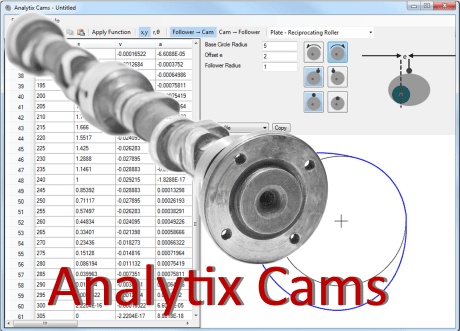
Analytix Cam
Analytix Cams enables mechanical engineers to quickly synthesize a cam profile given their follower motion requirements. Or...from an existing cam profile, the follower's geometry and kinematics can be quickly designed, fine-tuned and analyzed. With Analytix simulation software, you can optimize the cam/follower interaction with your mechanical system. Then export DXF to CAD or coordinate data to NC/CAM software.
Analytix Cams enables mechanical engineers to quickly synthesize a cam profile given their follower motion requirements. Or...from an existing cam profile, the follower's geometry and kinematics can be quickly designed, fine-tuned and analyzed. With Analytix simulation software, you can optimize the cam/follower interaction with your mechanical system. Then export DXF to CAD or coordinate data to NC/CAM software.
UNIT I
Four Exmples from Text Book will be given trainingOn software listed For the program
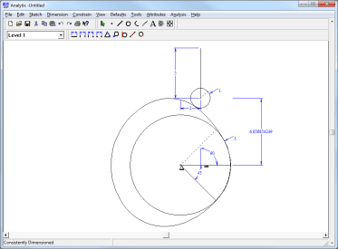
Here's how Analytix Cams is used to synthesize a cam profile. First, you choose the cam/follower type and such things as direction of rotation and follower offset. Then select a range of cam rotation, specify the starting and ending requirements for follower displacement, and the desired curve type (such as cycloidal, dwell, or constant acceleration).
Analytix/Cams then automatically synthesizes the precise points in between, taking into account all the geometry involved in that particular cam/follower configuration.
UNIT II
Four Exmples from Text Book will be given trainingOn software listed For the program
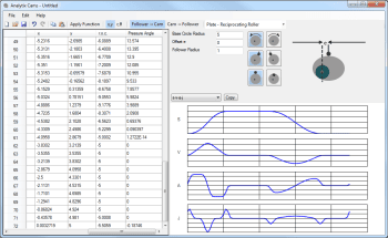
Kinematic and other data is automatically calculated and displayed in both tabular form and graphical form: displacement, velocity, acceleration, jerk, radius of curvature
UNIT IV
Four Exmples from Text Book will be given trainingOn software listed For the program
Duration 30 Hours
UNIT III
Four Exmples from Text Book will be given trainingOn software listed For the program
Analytix Linkage/Analytix 21
nalytix has been a favorite program of design engineers since the 1990's. We have finally done a long overdue overhaul of the software so that it is compatible with Windows 10 and 11. In addition, we've improved the user interface while keeping the core functionality familiar to our long-time users
UNIT I
Four Exmples from Text Book will be given trainingOn software listed For the program
Analytix is a sophisticated mechanism design-and-analysis software package for the PC that puts you, the engineer, back in control of the creative process.
By automating tedious, error-prone number-crunching analysis and giving you the instant visual feedback you need to do something more satisfying--improve your design.
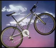
Mathematical Technology for Industry and EducatioWe create software for engineers and educators. We also provide software engineering consultation with expertise in:
- Numerical mathematical algorithms
- Symbolic mathematical algorithms
- Constraint based geometry
- Embedded physics
- Kinematics and dynamics
UNIT II
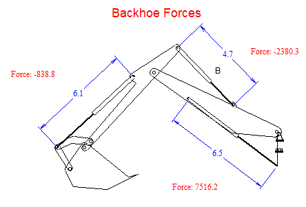
Four Exmples from Text Book will be given trainingOn software listed For the program
UNIT IV
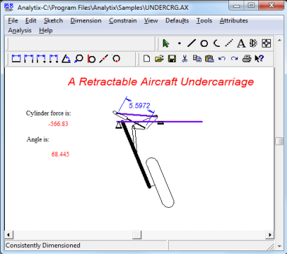
UNIT III
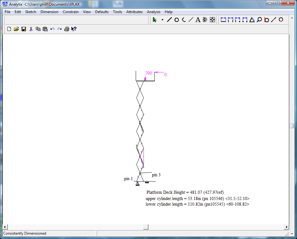
Four Exmples from Text Book will be given trainingOn software listed For the program
Physics Application Program