Industry Projects
Mechanical Projects Lifting and Conveying Equipment
Overhead Crane Gantry
Internship Program-Project Program-Product Dev, Program



UNIT I
Four Exmples from Text Book will be given trainingOn software listed For the program Four problem will be given for self training with software to Trainee
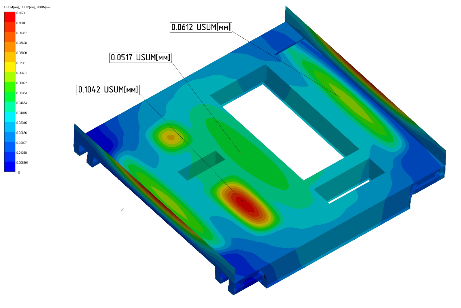
Specialists of the company R&D Center "APM" performed a strength calculation of the metal structure of the overhead crane.
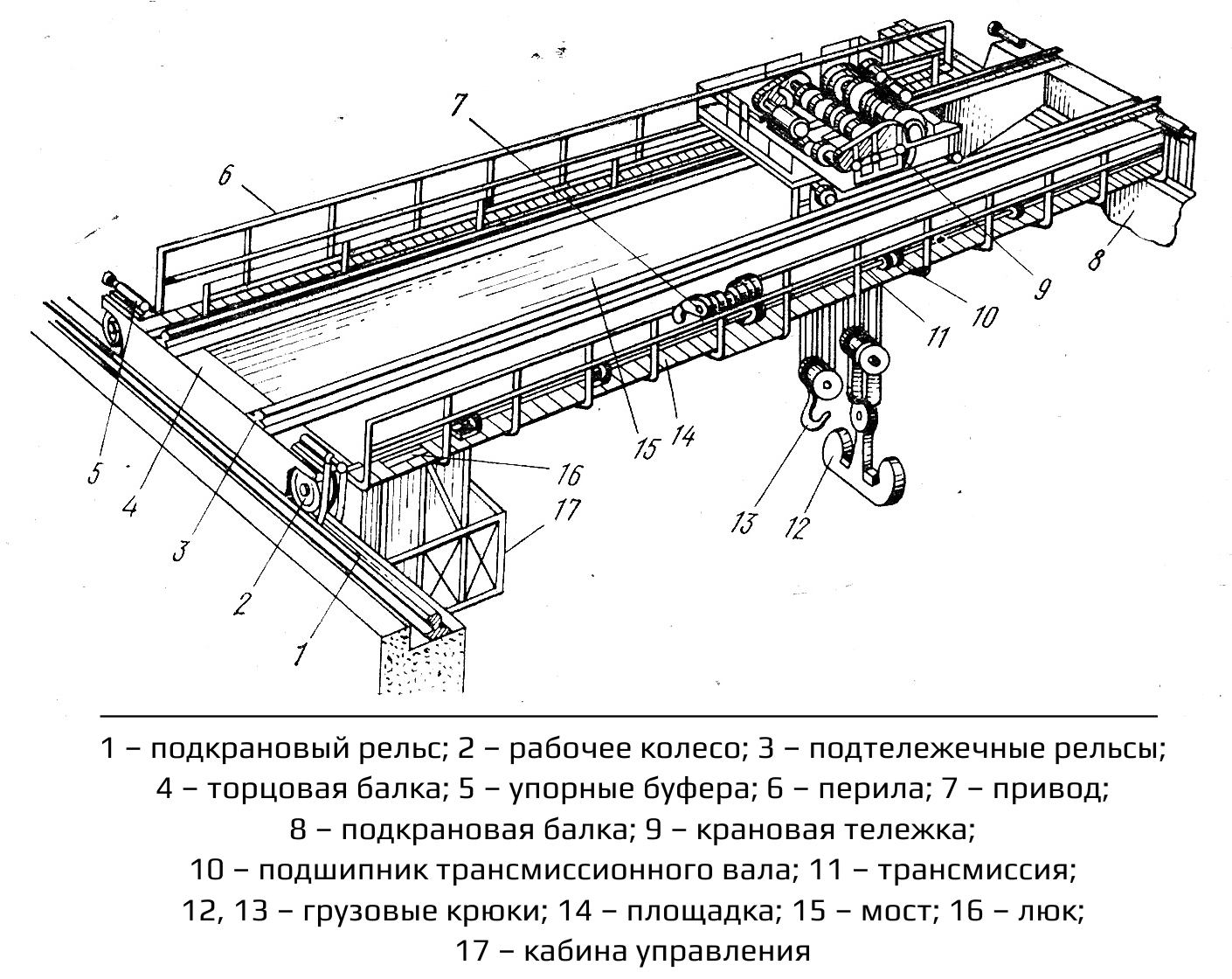
An overhead crane consists of two actually independent parts - a bridge and a cargo trolley. The strength calculation of these parts was carried out independently of each other, and the results of
UNIT IV
Four Exmples from Text Book will be given trainingOn software listed For the program Four problem will be given for self training with software to Trainee
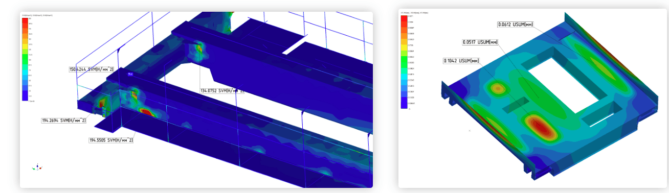
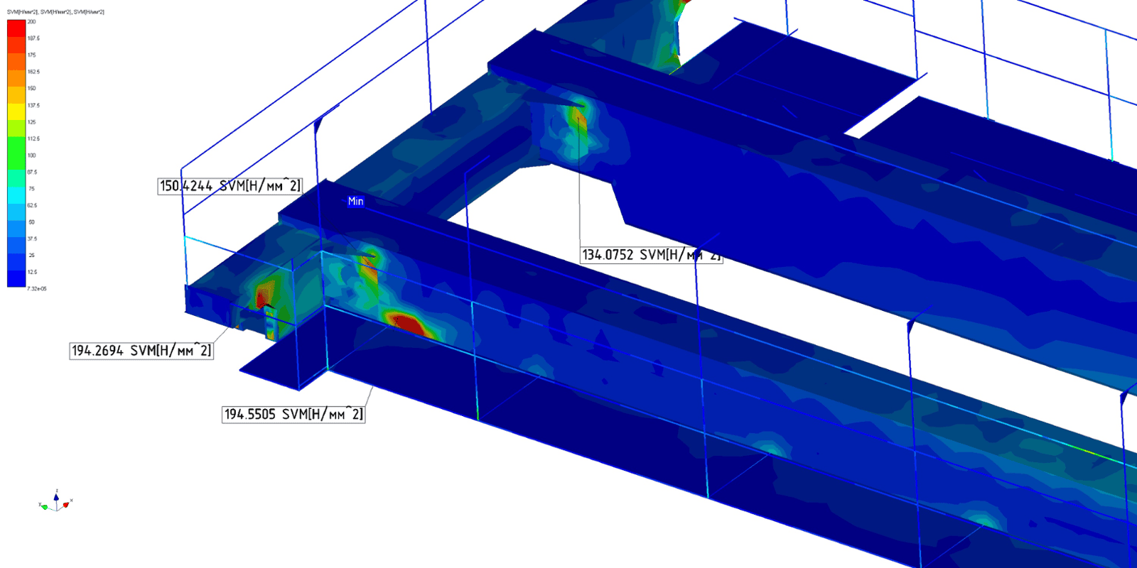
One of the results of the static calculation is a map of the equivalent stresses (according to Mises) of the crane bridge when the cargo trolley is in the middle of the span beam, as well as the cargo trolley itself.
After static analysis, the stability of the overhead crane structure model was calculated. The buckling shape allows you to determine the least stable structural member. In this case, the least stable elements are the plates of the bridge working platform, which are not affected by the main load.

UNIT II
Four Exmples from Text Book will be given trainingOn software listed For the program Four problem will be given for self training with software to Trainee
The calculation was carried out according to the requirements:
SNiP 2.01.07-85* Loads and Impacts.GOST 1451-77* (2003) Lifting cranes. Wind load. Norms and method of determination.SNiP II-23-81* Steel structures.
The calculation was carried out in the APM WinMachine software product.
Crane Bridge Calculation Results
The structure of span beams requires reinforcement due to the high level of stresses generated. The level of stress in other parts of the structure of the span and end beams of the bridge is very low. This means that there are significant reserves for improving the design and reducing its metal intensity. The margin of stability of the structure is sufficient. The least stable structural element is the plates of the decking of the work site, which are not affected by the main loads
UNIT III
Four Exmples from Text Book will be given trainingOn software listed For the program Four problem will be given for self training with software to Trainee
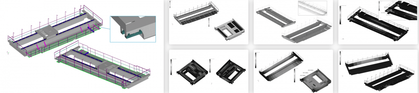
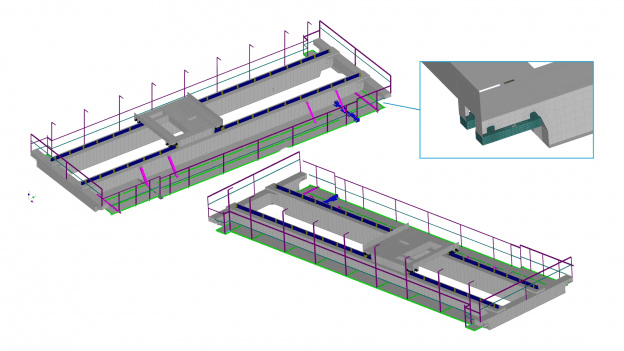
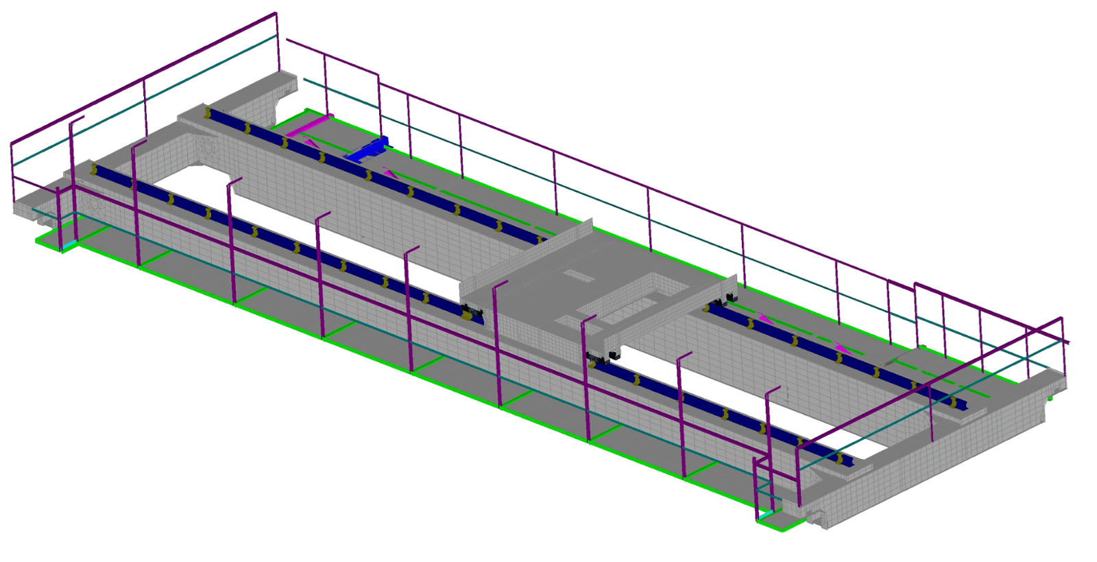
Calculation model
It was not possible to directly use the solid model provided by the customer for subsequent calculations. Since almost all structural elements are made of sheet metal, a very small partitioning step had to be selected to obtain reliable results. Calculating such a model using an ordinary personal computer could cause great difficulties. In this regard, all structural elements were modeled with plate finite elements, which made it possible to reduce the dimensionality of the problem from several million to 34,000 finite elements.