Industry Projects
Construction Projects
Bridge Structure Overpass Bridge
Internship Program-Project Program-Product Dev, Program


UNIT I
Four Exmples from Text Book will be given trainingOn software listed For the program Four problem will be given for self training with software to Trainee
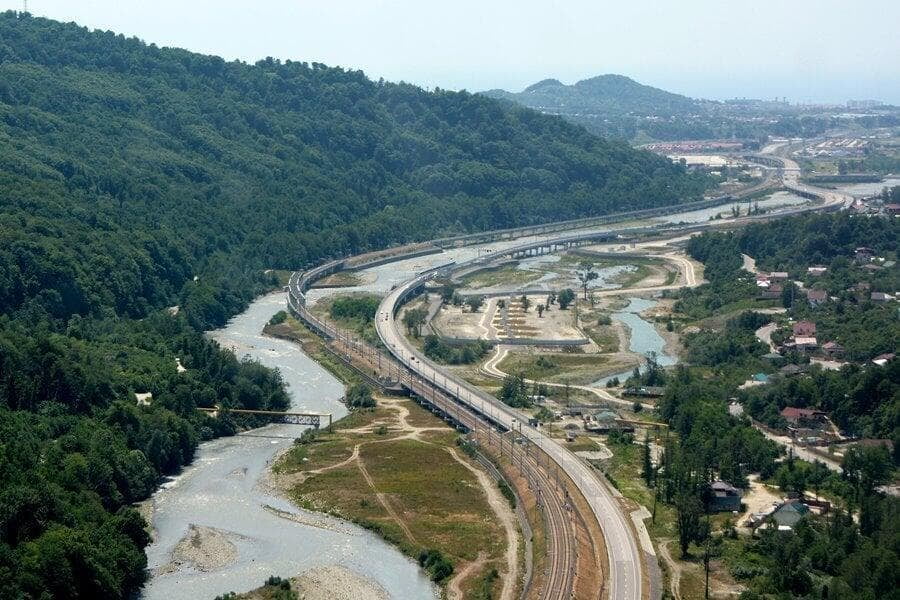
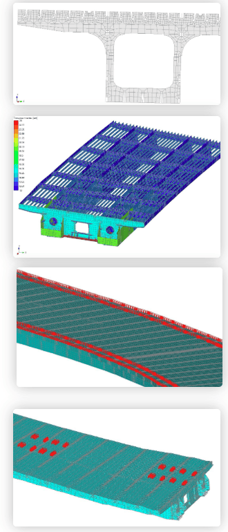
Specialists of the company STC "APM" by order of the Russian Ecological Fund "TECHECO" carried out verification calculations for the main and special (with seismic effects) load-bearing combinations of load-bearing metal structures of a number of transport structures of the combined (road and railway) road Adler - mountain resort "Alpika-Service".
Objects to be calculated:
Overpass C1 of traffic interchange No1 - PK1+95 - PK3+40
The overpass consists of one all-metal continuous span (3 spans between supports 1-4), made according to the scheme 40x2 + 55 m.
Overpass C2 of traffic interchange No1 - PK2+95 - PK6+90
The overpass consists of 2 all-metal continuous spans. The span structure PS1 has 5 spans (between supports 1-6), made according to the scheme 45 + 3x65 + 55 m.
Bridge - PK19+58 - PK20+02
The bridge is a steel-reinforced concrete beam continuous structure with one span of 33 m.
Overpass - PK38+33 - PK45+71
The overpass consists of 3 spans. The span structure PS1 steel-reinforced concrete beam continuous has 4 spans (between supports 1-5), made according to the scheme 4x63m. The overpass is designed for four lanes.
Bridge - PK47+23 - PK47+66
The bridge is a steel-reinforced concrete beam continuous structure with one span of 33 m.
Bridge - PC 49+85 - PC 54+61
The bridge is a steel-reinforced concrete beam continuous structure (9 spans), made according to the scheme 3x42 + 4 x 63 + 2 x 42 m. with widening. The bridge is designed for four lanes.
Overpass of the transport interchange No2 - PK56+42 - PK58+56
The overpass consists of one steel-reinforced concrete beam continuous span structure (4 spans between supports 1-5), made according to the scheme 42 + 63x2 + 42 m.
Overpass of the transport interchange No2 next to the existing road - PK57+30 o.h.
The overpass consists of one steel beam continuous span structure (3 spans between supports 1-4), made according to the scheme 3x63m. The overpass is designed for one lane.
The calculation was carried out in accordance with the current regulatory documents:
SNiP 2.01.07-85 Loads and impacts;SNiP 2.05.03-84*(2000, 2008) Bridges and pipes;SNiP II-7-81*(2000) Construction in seismic areas;GOST R 52748-2007 Public Roads.
The calculation was carried out in the APM CivilEngineering software product.
UNIT IV
Four Exmples from Text Book will be given trainingOn software listed For the program Four problem will be given for self training with software to Trainee
Estimation of the bearing capacity of the metal structure of bridges and spans according to the second group of limit states.Vertical elastic deflections of the superstructure for the span do not exceed the permissible ones.
Evaluation of modal analysis results.The design periods of natural oscillations of the calculated elements (in the unloaded state) for the two lower shapes do not lie in the range of values of 0.45 - 0.60 s (1.67...2.22 Hz) - in the vertical plane and in the range of 0.9 - 1.2 s (0.83...1.11 Hz) - in the horizontal transverse plane. Consequently, all the requirements according to SNiP 2.05.03-84* are met.
Assessment of the bearing capacity of the metal structure of the superstructure according to the first group of limit states (special load combinations).The maximum equivalent stresses estimated by the Guber-Mises strength hypothesis do not exceed the permissible stresses. This allows us to conclude that the yield strength condition is fulfilled with a margin.

UNIT II
Four Exmples from Text Book will be given trainingOn software listed For the program Four problem will be given for self training with software to Trainee
The structural analysis was carried out for the following loads and effects:
Constant - the weight of the structure, the weight of the asphalt concrete pavement, the weight of barrier and railings, noise barriers, lighting poles, observation passages and drainage systems;Loads from pedestrians;Moving loads - distributed and concentrated components (AK 14), single and double (NK 100);Seismic action in all directions.
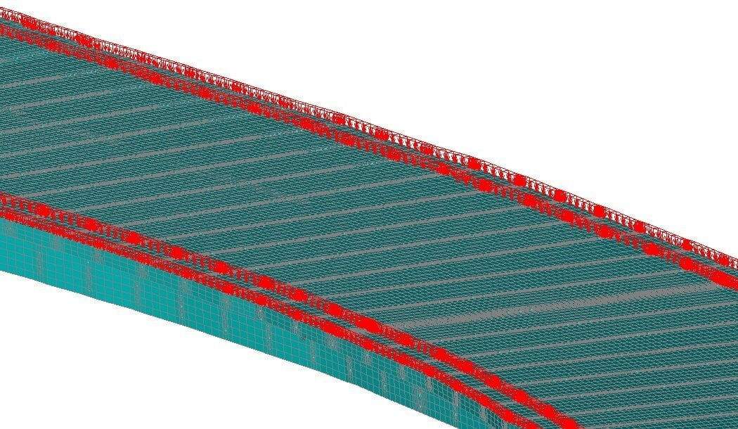
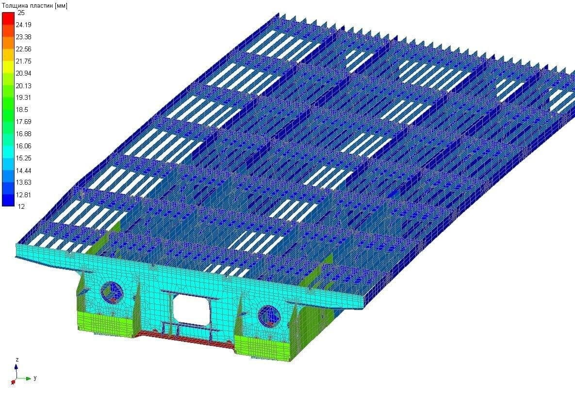
Structural modeling was performed in the APM Structure3D module of the APM Civil Engineering system.
Models were built with plate end elements.
UNIT III
Four Exmples from Text Book will be given trainingOn software listed For the program Four problem will be given for self training with software to Trainee
1. Basic Design Load Combinations
Moving Load AC 14:Constant* 1.1 + Pedestrians* 1.2 + AC14r*1.38 + AC14c.i*1.38with moving load NK 100:
Constant* 11 + NC 100i* 1.1Constant* 1.1 + 2*NC100i*0.825
2. Main combinations of standard loads
Moving Load AC 14:Constant + Pedestrians + AC14r + AC14c.iNK 100:DC + NK 100iDC + 2*NC100i
3. Special combinations of design loads
Non-Moving LoadConstant* 1.1 + Seismic Y*1Constant* 1.1 + Seismic Z*1Movable Constant* 1.1 + Pedestrians*0.36 - AK14p*0.36 + AK14s.i*0.36 + Seismic Z*0.8Constant* 1.1 + Pedestrians*0.36 + AK14p*0.36 + AK14c.i*0.36 + Seismic Y*0.8
As a result of calculations under constant loads, the following were determined:
equivalent Mises stresses;stiffness;reactions of all-round supports.
Calculations were made for special load combinations:
modal analysis (the forms of oscillations are determined);strength analysis (equivalent Mises stresses, stiffness).