Industry Projects
Mechanical Projects Emtertainment
Ferris Wheel
Internship Program-Project Program-Product Dev, Program

APM WINMACHINE APM CIVIL APM FEM

UNIT I
Four Exmples from Text Book will be given trainingOn software listed For the program Four problem will be given for self training with software to Trainee
50m Ferris Wheel
The calculation of the Ferris wheel was carried out by order of NTP SIO LLC.
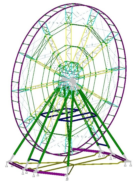
The bearing system of the attraction is a collapsible spatial rod structure of a combined type.
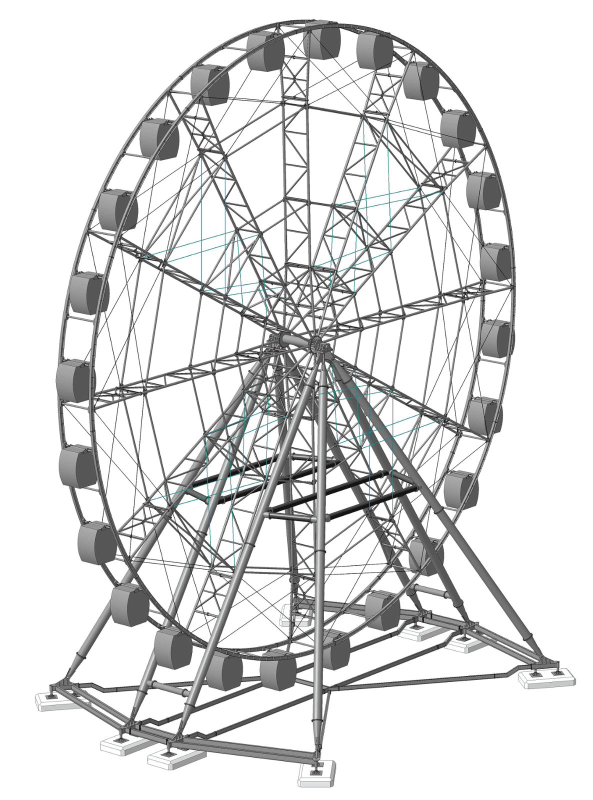
The frame of the Ferris wheel is made in the form of a polar-symmetrical cyclic rod system consisting of: radial trusses; ring belts; paths, as well as connecting them connections and anti-seismic tripwires.
The horizontal axis of the Ferris wheel is hinged to the support legs, which in turn are hinged to the prefabricated steel base.
Technical parameters and characteristics of the ride:
Dimensions:
height: 49,500 mm;wheel diameter along the axes of the cab suspension: 45,500 mm;Width (at the edges of the supports): 28,500 mm.
Method of installation of the ride: foundationless structure.
The calculation of the Ferris wheel was carried out by order of NTP SIO LLC.
The bearing system of the attraction is a collapsible spatial rod structure of a combined type.
The frame of the Ferris wheel is made in the form of a polar-symmetrical cyclic rod system consisting of: radial trusses; ring belts; paths, as well as connecting them connections and anti-seismic tripwires.
The horizontal axis of the Ferris wheel is hinged to the support legs, which in turn are hinged to the prefabricated steel base.
Technical parameters and characteristics of the ride:
Dimensions:
height: 49,500 mm;wheel diameter along the axes of the cab suspension: 45,500 mm;Width (at the edges of the supports): 28,500 mm.
Method of installation of the ride: foundationless structure.
UNIT IV
Four Exmples from Text Book will be given trainingOn software listed For the program Four problem will be given for self training with software to Trainee
Results of the completed project
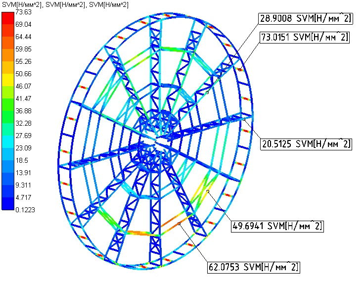
The static analysis performed made it possible to determine the mechanical state of the attraction structure as a single load-bearing spatial system within the framework of linear relationships between stresses and deformations and to obtain estimates of its strength and rigidity under the action of the design loads provided for in the technical specification using the limit state method of the first group.
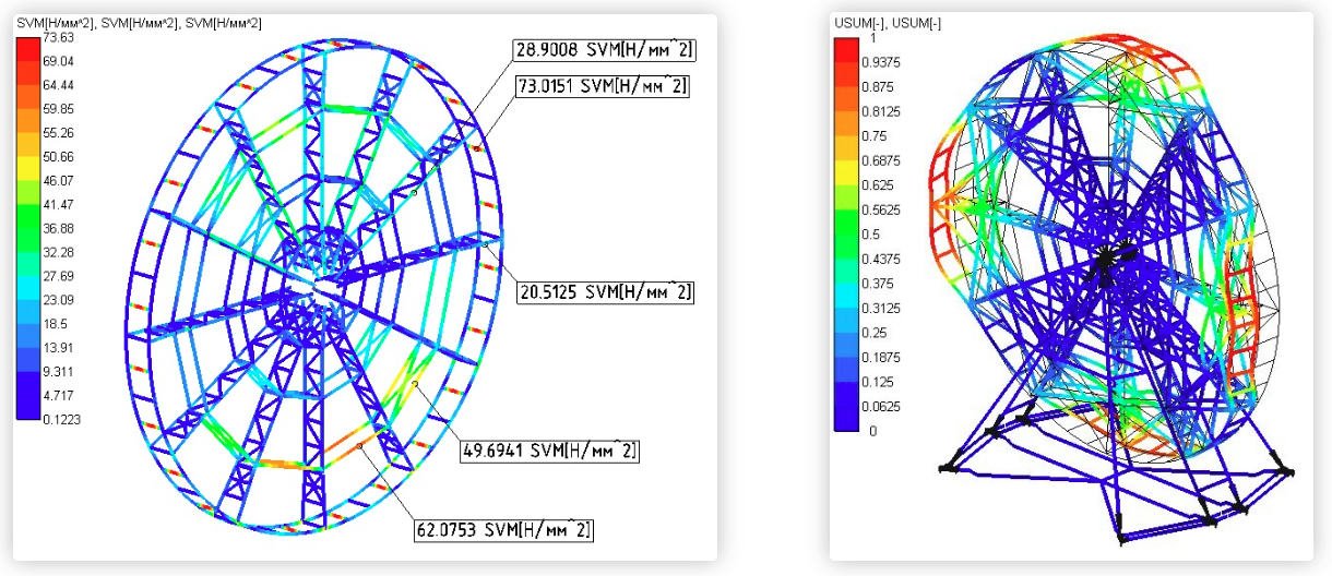
Based on the analysis of finite element models, it was established that the stress-strain state of the structure under the action of design loads has a heterogeneous nature, which most significantly depends on two components of the mechanical load - the own weight of the structure and wind pressure. The effect of the load on the weight of passengers is insignificant, its maximum effect is estimated to be within 5%. Therefore, the nature of the distribution of internal forces, stresses and deformations depends to a greater extent on the position of the structural element and to a lesser extent on the level of loading of the attraction by passengers.
The static analysis performed made it possible to determine the mechanical state of the attraction structure as a single load-bearing spatial system within the framework of linear relationships between stresses and deformations and to obtain estimates of its strength and rigidity under the action of the design loads provided for in the technical specification using the limit state method of the first group.
Based on the analysis of finite element models, it was established that the stress-strain state of the structure under the action of design loads has a heterogeneous nature, which most significantly depends on two components of the mechanical load - the own weight of the structure and wind pressure. The effect of the load on the weight of passengers is insignificant, its maximum effect is estimated to be within 5%. Therefore, the nature of the distribution of internal forces, stresses and deformations depends to a greater extent on the position of the structural element and to a lesser extent on the level of loading of the attraction by passengers.


UNIT II
Four Exmples from Text Book will be given trainingOn software listed For the program Four problem will be given for self training with software to Trainee
Calculation model
The design scheme of the attraction is built on the basis of a 3D model provided by the customer.
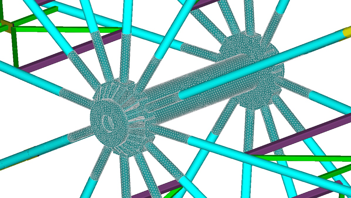
The structural elements were modeled with rod and volumetric end elements.
When modeling the behavior of the load-bearing structure, the option of fixing it on a prefabricated steel base was considered. The external relations of the system were reproduced by setting restrictions on the displacement of supports relative to the global Cartesian coordinate system. The fixation of the calculation model was carried out by imposing restrictions on the linear displacements of sixteen nodal reference points.
The internal connections of the system simulated the conditions of connections of the structural elements of the attraction. In the developed calculation model, the following were implemented:
articulated connection of the central shaft with the drum;rigid connection of the tracks with support posts in the places where electric drives are installed;hinged connection of radial trusses with ring belts and anti-seismic tripwires;rigid connection of radial trusses to the drum;articulated connection of the shaft of passenger cabins with wheel tracks;hinged connection of the support legs with the base of the central shaft and the prefabricated base;rigid joints of the beams of the prefabricated base.
The design scheme of the attraction is built on the basis of a 3D model provided by the customer.
The structural elements were modeled with rod and volumetric end elements.
When modeling the behavior of the load-bearing structure, the option of fixing it on a prefabricated steel base was considered. The external relations of the system were reproduced by setting restrictions on the displacement of supports relative to the global Cartesian coordinate system. The fixation of the calculation model was carried out by imposing restrictions on the linear displacements of sixteen nodal reference points.
The internal connections of the system simulated the conditions of connections of the structural elements of the attraction. In the developed calculation model, the following were implemented:
articulated connection of the central shaft with the drum;rigid connection of the tracks with support posts in the places where electric drives are installed;hinged connection of radial trusses with ring belts and anti-seismic tripwires;rigid connection of radial trusses to the drum;articulated connection of the shaft of passenger cabins with wheel tracks;hinged connection of the support legs with the base of the central shaft and the prefabricated base;rigid joints of the beams of the prefabricated base.
UNIT III
Four Exmples from Text Book will be given trainingOn software listed For the program Four problem will be given for self training with software to Trainee
Calculation results
The static design of the Ferris wheel ride was performed on the main and special load combinations, for thirty design cases (load case combinations). Maps of the stressed and deformed state of the structure under the corresponding load variants are obtained.
The calculation for fatigue under the action of standard load values taking into account the coefficient of dynamism is carried out.
An assessment of the maximum deflections of the amusement ride structure is carried out in accordance with GOST R 52170-2003.
The calculation of structural elements according to SNiP II-23-81* for each type of elements in the most loaded area of the structure for the operating mode of the attraction is also carried out.
According to GOST R 52170-2003, the static stability of the attraction structure (shape stability) was calculated.
The static design of the Ferris wheel ride was performed on the main and special load combinations, for thirty design cases (load case combinations). Maps of the stressed and deformed state of the structure under the corresponding load variants are obtained.
The calculation for fatigue under the action of standard load values taking into account the coefficient of dynamism is carried out.
An assessment of the maximum deflections of the amusement ride structure is carried out in accordance with GOST R 52170-2003.
The calculation of structural elements according to SNiP II-23-81* for each type of elements in the most loaded area of the structure for the operating mode of the attraction is also carried out.
According to GOST R 52170-2003, the static stability of the attraction structure (shape stability) was calculated.