Industry Projects
Mechanical Projects Oil & Gas Equipment
Ball Valve
Internship Program-Project Program-Product Dev, Program
APM WINMACHINE APM CIVIL APM FEM

UNIT I
Four Exmples from Text Book will be given trainingOn software listed For the program Four problem will be given for self training with software to Trainee
Ball valve
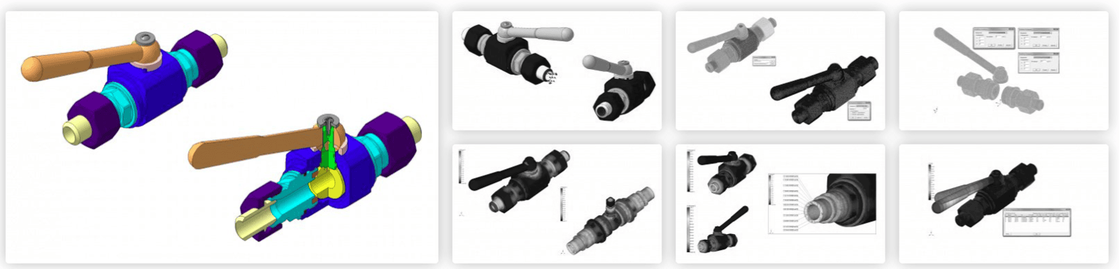
The company STC "APM" carried out calculations of the strength and seismic resistance of the ball valve Dn15 Pn160 taking into account the requirements of GOST 30546.1.
The preparation of the calculation model was carried out using APM FEM – a finite element strength analysis system for KOMPAS-3D. The calculation was carried out using the APMStructure3D module, which is part of the CAD/CAE calculation complex of the APM WinMachine computer-aided calculation and design system for mechanical equipment and structures.
The design analysis was carried out by order of NPO "Armgazinvest" LLC.
The company STC "APM" carried out calculations of the strength and seismic resistance of the ball valve Dn15 Pn160 taking into account the requirements of GOST 30546.1.
The preparation of the calculation model was carried out using APM FEM – a finite element strength analysis system for KOMPAS-3D. The calculation was carried out using the APMStructure3D module, which is part of the CAD/CAE calculation complex of the APM WinMachine computer-aided calculation and design system for mechanical equipment and structures.
The design analysis was carried out by order of NPO "Armgazinvest" LLC.
UNIT IV
Four Exmples from Text Book will be given trainingOn software listed For the program Four problem will be given for self training with software to Trainee
Results of the completed project
Analyzing the presented results for all calculated model load cases, the following conclusions can be drawn:
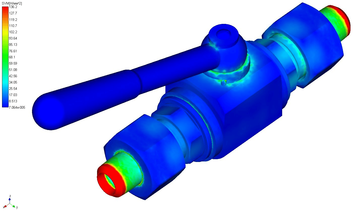
The maximum equivalent stresses estimated by the Huber-Mises strength hypothesis (strength theory 4) occur in nipples at a working medium temperature of -600C.Comparing the maximum effective stresses with the permissible yield strength for 09G2S steel, it can be considered that the structural strength condition is met.Seismic action does not make a significant contribution to the overall picture of the stress-strain state of the crane, since the level of stresses from the action of the seismic load both along the axis of the nozzles and perpendicular to the axis of the nozzles does not exceed 1 MPa.The maximum equivalent stresses estimated by the Huber-Mises strength hypothesis (strength theory 4) occur in nipples at a working medium temperature of -600C, in case of seismic action along the axis of the nozzles.Comparing the maximum effective stresses with the permissible yield strength for 09G2S steel of 325 MPa, it can be assumed that the condition of structural strength is met.
The work carried out showed the applicability of APM software complexes for solving complex problems of strength analysis of various structures in the oil and gas industry.
Analyzing the presented results for all calculated model load cases, the following conclusions can be drawn:
The maximum equivalent stresses estimated by the Huber-Mises strength hypothesis (strength theory 4) occur in nipples at a working medium temperature of -600C.Comparing the maximum effective stresses with the permissible yield strength for 09G2S steel, it can be considered that the structural strength condition is met.Seismic action does not make a significant contribution to the overall picture of the stress-strain state of the crane, since the level of stresses from the action of the seismic load both along the axis of the nozzles and perpendicular to the axis of the nozzles does not exceed 1 MPa.The maximum equivalent stresses estimated by the Huber-Mises strength hypothesis (strength theory 4) occur in nipples at a working medium temperature of -600C, in case of seismic action along the axis of the nozzles.Comparing the maximum effective stresses with the permissible yield strength for 09G2S steel of 325 MPa, it can be assumed that the condition of structural strength is met.
The work carried out showed the applicability of APM software complexes for solving complex problems of strength analysis of various structures in the oil and gas industry.
UNIT II
Four Exmples from Text Book will be given trainingOn software listed For the program Four problem will be given for self training with software to Trainee
Calculation
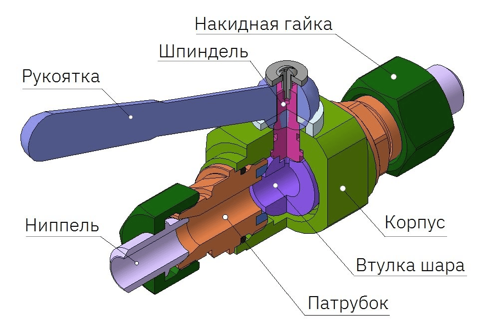
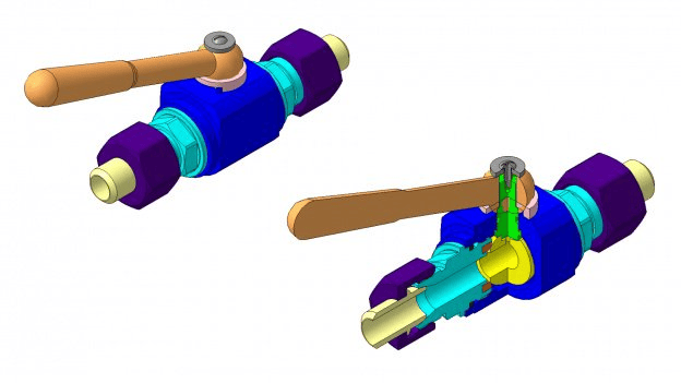
Finite element models of the ball valve structure are created on the basis of 3D models made in KOMPAS 3D and transferred by the customer in accordance with the terms of reference.
The pressure from the working medium is simulated by a uniformly distributed load of 16 MPa applied to the respective surfaces.
The design load from the piping side acts as a tensile distributed force applied to the end of the first nozzle, whereas the end of the second nozzle is fixed in this direction.
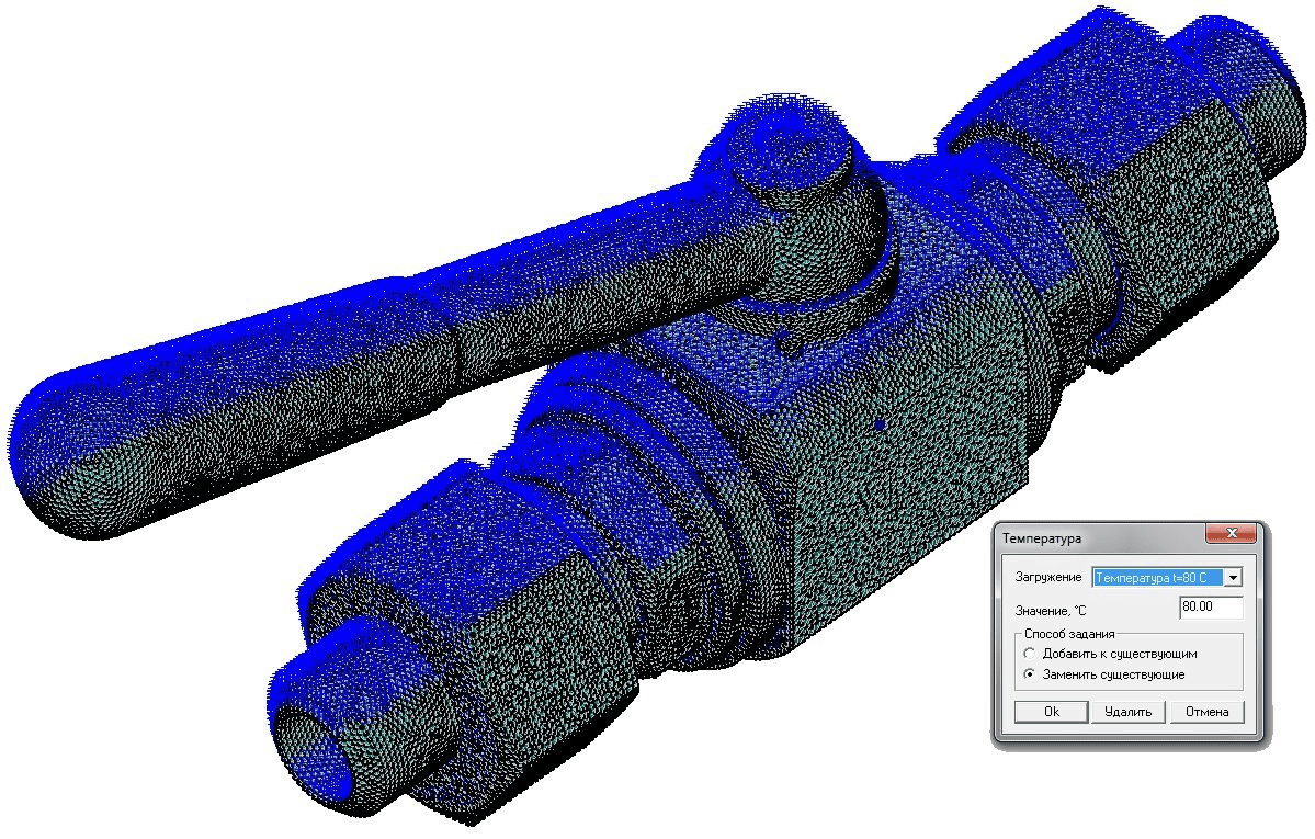
To take into account thermoelastic deformations, the crane structure is heated to +80 0C, as well as cooling the elements of the ball valve to -60 0C, which corresponds to the extreme temperature conditions of the working environment.
The calculation module takes into account the own weight automatically, based on the geometry of the crane elements and the density of the material, by entering a self-weight multiplier equal to one.
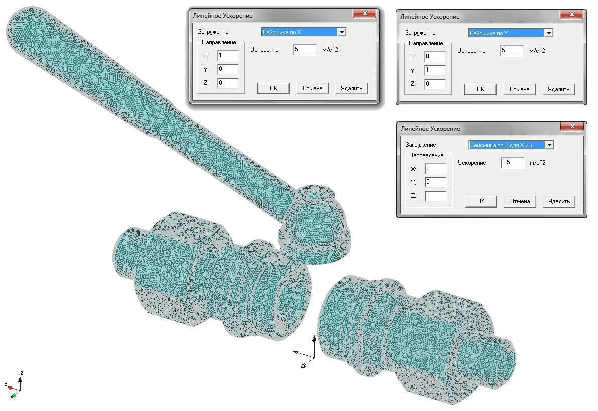
In accordance with GOST 30546.1-98, the value of the calculated maximum acceleration in the horizontal direction will be 5 m/s2, respectively, the value of vertical acceleration will be 3.5 m/s2.
Linear acceleration is set in two directions, along and perpendicular to the axis of the nozzles.
For a comprehensive assessment of the stress-strain state, the following calculation cases were considered:
the combined action of overpressure, pipeline forces, self-weight, as well as heating up to +80°C0C;the combined action of overpressure, pipeline forces, self-weight, as well as cooling to -600C;Combined action of overpressure, pipeline forces, self-weight, fluid temperature +800C, seismic action along the axis of the nozzle;Combined action of overpressure, pipeline forces, self-weight, fluid temperature +800C, seismic action perpendicular to the axis of the nozzle;Combined action of overpressure, pipeline forces, self-weight, working medium temperature -600C, seismic action along the axis of the nozzle;Combined action of overpressure, pipeline forces, self-weight, working medium temperature -600C, the seismic action is perpendicular to the axis of the spigot.
Finite element models of the ball valve structure are created on the basis of 3D models made in KOMPAS 3D and transferred by the customer in accordance with the terms of reference.
The pressure from the working medium is simulated by a uniformly distributed load of 16 MPa applied to the respective surfaces.
The design load from the piping side acts as a tensile distributed force applied to the end of the first nozzle, whereas the end of the second nozzle is fixed in this direction.
To take into account thermoelastic deformations, the crane structure is heated to +80 0C, as well as cooling the elements of the ball valve to -60 0C, which corresponds to the extreme temperature conditions of the working environment.
The calculation module takes into account the own weight automatically, based on the geometry of the crane elements and the density of the material, by entering a self-weight multiplier equal to one.
In accordance with GOST 30546.1-98, the value of the calculated maximum acceleration in the horizontal direction will be 5 m/s2, respectively, the value of vertical acceleration will be 3.5 m/s2.
Linear acceleration is set in two directions, along and perpendicular to the axis of the nozzles.
For a comprehensive assessment of the stress-strain state, the following calculation cases were considered:
the combined action of overpressure, pipeline forces, self-weight, as well as heating up to +80°C0C;the combined action of overpressure, pipeline forces, self-weight, as well as cooling to -600C;Combined action of overpressure, pipeline forces, self-weight, fluid temperature +800C, seismic action along the axis of the nozzle;Combined action of overpressure, pipeline forces, self-weight, fluid temperature +800C, seismic action perpendicular to the axis of the nozzle;Combined action of overpressure, pipeline forces, self-weight, working medium temperature -600C, seismic action along the axis of the nozzle;Combined action of overpressure, pipeline forces, self-weight, working medium temperature -600C, the seismic action is perpendicular to the axis of the spigot.
UNIT III
Four Exmples from Text Book will be given trainingOn software listed For the program Four problem will be given for self training with software to Trainee
alculation results
The stress-strain state analysis of the load-bearing elements of the ball valve structure was carried out in a geometrically and physically linear setting using the finite element method in the APM Structure3D module.
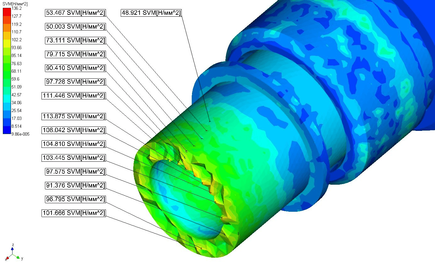
Pronounced concentrators at the ends of the nipple are characterized by the presence of supports that have significantly increased the rigidity of the fixing zones, which is not observed in the real design. However, the presence of supports is a necessary condition for solving the problem of determining the stress-strain state of a ball valve.
To determine the effective stresses, we exclude zones with edge effects using the San Venan principle: for the problem of solid modeling, we ignore at least four finite element layers along the nipple axis, starting from the outermost support end.
Color maps of the results of the stress-strain analysis for the Dn15 Pn160 ball valve are given with the exception of the display of zones, according to the San Venan principle.
The stress-strain state analysis of the load-bearing elements of the ball valve structure was carried out in a geometrically and physically linear setting using the finite element method in the APM Structure3D module.
Pronounced concentrators at the ends of the nipple are characterized by the presence of supports that have significantly increased the rigidity of the fixing zones, which is not observed in the real design. However, the presence of supports is a necessary condition for solving the problem of determining the stress-strain state of a ball valve.
To determine the effective stresses, we exclude zones with edge effects using the San Venan principle: for the problem of solid modeling, we ignore at least four finite element layers along the nipple axis, starting from the outermost support end.
Color maps of the results of the stress-strain analysis for the Dn15 Pn160 ball valve are given with the exception of the display of zones, according to the San Venan principle.