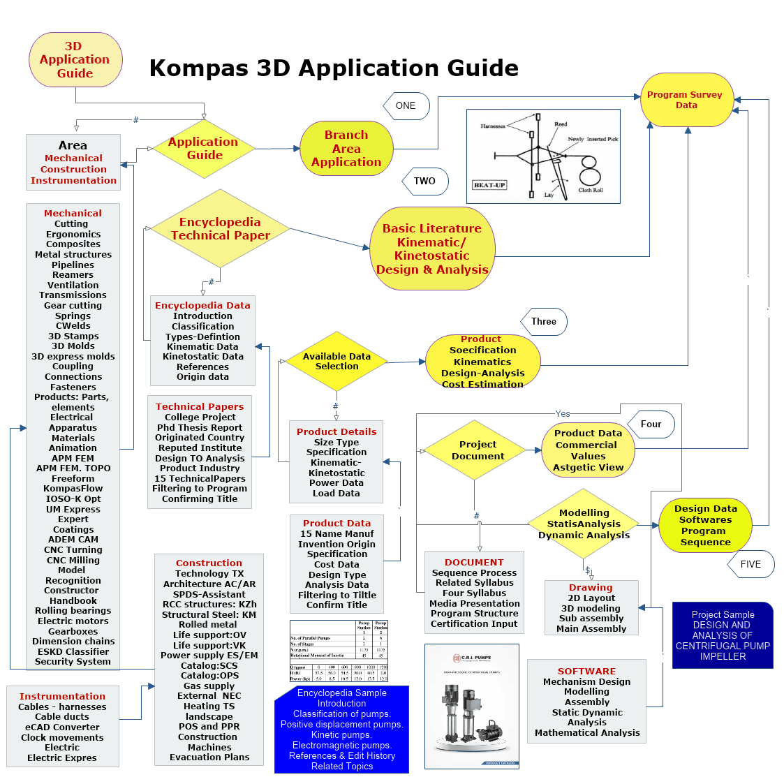
Kompas 3D Instrumentation Application
Women Graduates are trained with basics in Industry application from basic science Mathematics, Physics, Chemistry
Training in application Software by Industry Professional, to train others with preparation as TRAINER to empower.
Empowering areas are ACADEMIC SERVICE-ENTREPRENEURSHIP-DESIGN SERVICE-INDUSTRIES-SOCIAL ENGINEERING
Syllabus Program-Internship Program-Project Program-Product Dev, Program
KOMPAS 3D Application

Instrumentation
UNIT I
Four Exmples from Text Book will be given trainingOn software listed For the program Four problem will be given for self training with software to Trainee
Four Exmples from Text Book will be given trainingOn software listed For the program Four problem will be given for self training with software to Trainee
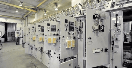
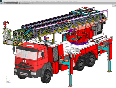
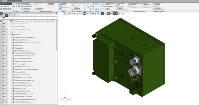
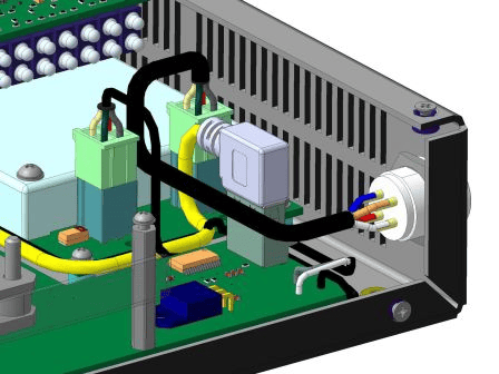
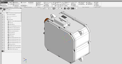
Equipment: Cables and harnesses
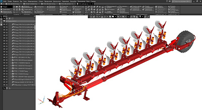
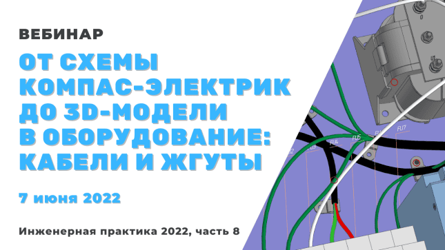
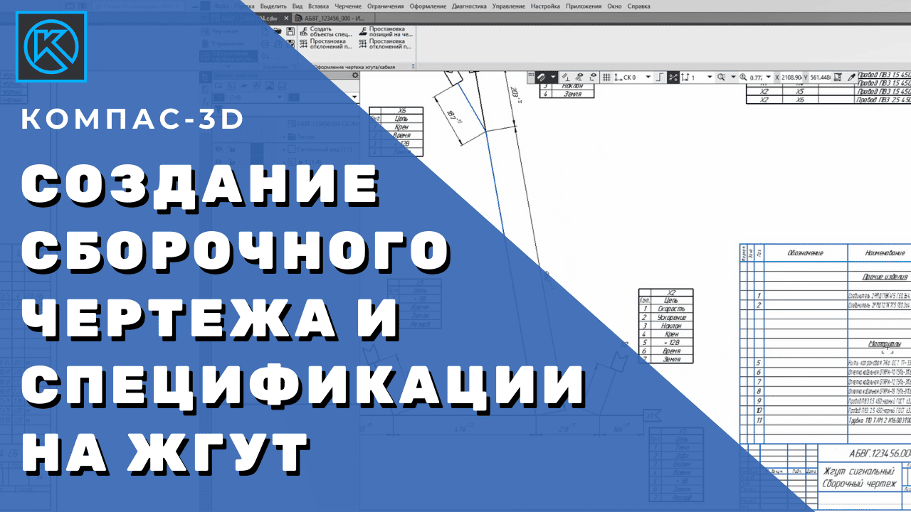
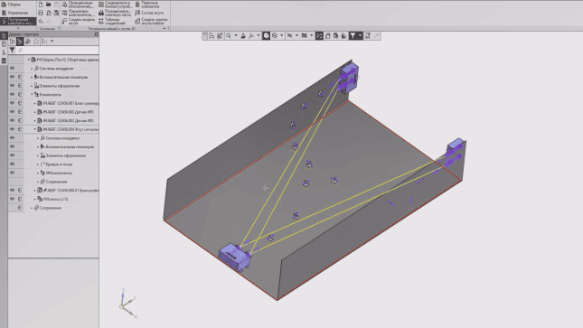
A specialized application for KOMPAS-3D, designed to automate the process of three-dimensional modeling of electrical cables and harnesses, as well as to issue design documentation for these products.
UNIT II
Four Exmples from Text Book will be given trainingOn software listed For the program Four problem will be given for self training with software to Trainee
The app automatically creates:
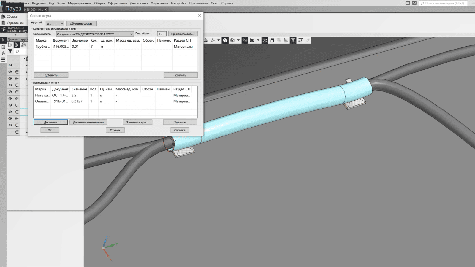
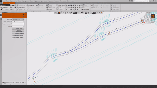
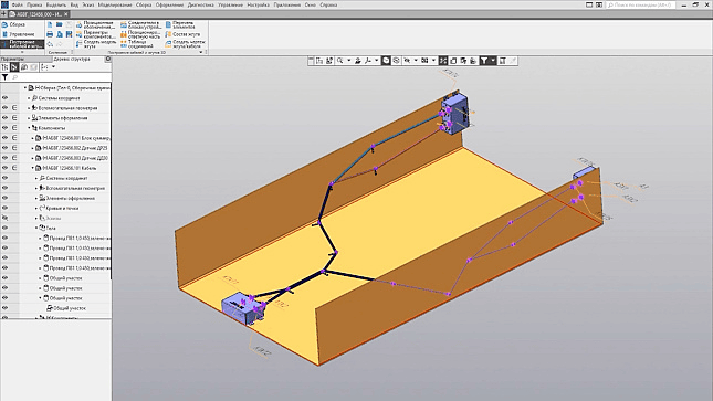
routes for laying cables and harnesses in the product space;positioning of cable parts of connectors by their instrument (block) parts;three-dimensional models of cables and harnesses, taking into account the number and diameter of conductors passing along the routes;rounding at the points of rotation of the route, taking into account the automatically calculated nominal diameter of the cable or harness branch;assembly drawing of the cable or harness;specification for the drawing with the calculation of the lengths of all conductors and the number of different materials;Designations on the assembly drawing;Assembly Unit BOM objects for harnesses or cables.
routes for laying cables and harnesses in the product space;positioning of cable parts of connectors by their instrument (block) parts;three-dimensional models of cables and harnesses, taking into account the number and diameter of conductors passing along the routes;rounding at the points of rotation of the route, taking into account the automatically calculated nominal diameter of the cable or harness branch;assembly drawing of the cable or harness;specification for the drawing with the calculation of the lengths of all conductors and the number of different materials;Designations on the assembly drawing;Assembly Unit BOM objects for harnesses or cables.
Equipment: Cables and harnesses
UNIT III
Four Exmples from Text Book will be given trainingOn software listed For the program Four problem will be given for self training with software to Trainee
Equipment: Cables and harnesses
Equipment: Cables and harnesses
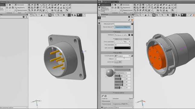
Any 3D model source can be used as a component database. These can be individual 3D model files, model libraries, and catalogs of the Standard Product Library.
As a database of wires and cables, you can use both special text files as part of the application and the Materials and Assortment Library.
The dimensions in the resulting drawings fully correspond to the dimensions of cables and harnesses measured along the axes of their three-dimensional models. The total length of the conductors in the specification additionally takes into account all mounting allowances and sags set by the user at the stage of routing formation. Users can add tables to connector models with pins, their corresponding signals, and lead wire markings. At the same time, data from the units and devices on the addresses of electrical communication and signals are automatically transmitted to the cable parts of the harnesses.
As a database of wires and cables, you can use both special text files as part of the application and the Materials and Assortment Library.
The dimensions in the resulting drawings fully correspond to the dimensions of cables and harnesses measured along the axes of their three-dimensional models. The total length of the conductors in the specification additionally takes into account all mounting allowances and sags set by the user at the stage of routing formation. Users can add tables to connector models with pins, their corresponding signals, and lead wire markings. At the same time, data from the units and devices on the addresses of electrical communication and signals are automatically transmitted to the cable parts of the harnesses.
UNIT IV
Four Exmples from Text Book will be given trainingOn software listed For the program Four problem will be given for self training with software to Trainee
Equipment: Cables and harnesses
Equipment: Cables and harnesses
On the assembly drawing of the harness or cable, the designer can place connector soldering tables if necessary.
The application is used in instrumentation to model connections between blocks and connectors in general, as well as in electrical engineering, where connections between individual contacts must be modeled.
The Cables and Harnesses application is integrated with the electrical equipment design systems KOMPAS-Electric and E3 in terms of importing the composition of electrical devices — the List of Elements — in the form of an XML file.
Manufacturer: ASCON-Design SystemsLLC Requires for work: KOMPAS-3DSystem requirements correspond to KOMPAS-3D system requirements
The application is used in instrumentation to model connections between blocks and connectors in general, as well as in electrical engineering, where connections between individual contacts must be modeled.
The Cables and Harnesses application is integrated with the electrical equipment design systems KOMPAS-Electric and E3 in terms of importing the composition of electrical devices — the List of Elements — in the form of an XML file.
Manufacturer: ASCON-Design SystemsLLC Requires for work: KOMPAS-3DSystem requirements correspond to KOMPAS-3D system requirements
KOMPAS 3D Application
Instrumentation
UNIT I
Four Exmples from Text Book will be given trainingOn software listed For the program Four problem will be given for self training with software to Trainee
Four Exmples from Text Book will be given trainingOn software listed For the program Four problem will be given for self training with software to Trainee
Equipment: Cable ducts
Equipment: Cable ducts
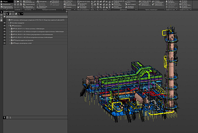
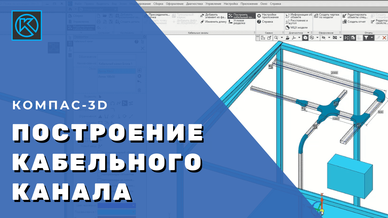
Equipment: Cable ducts are a specialized KOMPAS-3D application for rapid design of branched channels of cable systems.
UNIT II
Four Exmples from Text Book will be given trainingOn software listed For the program Four problem will be given for self training with software to Trainee
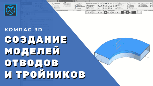
The application allows you to quickly build cable channels without a pre-created path. In the places of turning and branching, bends and tees are automatically installed according to the style of the cable channel.
It is recommended that you start building after the main equipment models are placed in the project. A cable duct can start and end at any point in space, including a connection point or connection point.
It is recommended that you start building after the main equipment models are placed in the project. A cable duct can start and end at any point in space, including a connection point or connection point.
Equipment: Cable ducts
Equipment: Cable ducts
UNIT III
Four Exmples from Text Book will be given trainingOn software listed For the program Four problem will be given for self training with software to Trainee
Equipment: Cable ducts
Equipment: Cable ducts
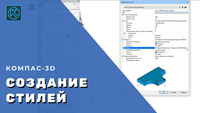
The connection point contains the parameters of the cable duct cross-section and is used to quickly select a style.
In the style, you can specify a set of fasteners for connecting cable channels. The application will automatically calculate the required number of fasteners depending on the length of the channels. No fastener models are created, which does not load the model. Fasteners can be added to the kit from help systems, files, or entered manually.
In the process of work, you can manually add elements that will be part of the cable duct.
In the style, you can specify a set of fasteners for connecting cable channels. The application will automatically calculate the required number of fasteners depending on the length of the channels. No fastener models are created, which does not load the model. Fasteners can be added to the kit from help systems, files, or entered manually.
In the process of work, you can manually add elements that will be part of the cable duct.
UNIT IV
Four Exmples from Text Book will be given trainingOn software listed For the program Four problem will be given for self training with software to Trainee
Equipment: Cable ducts
Equipment: Cable ducts
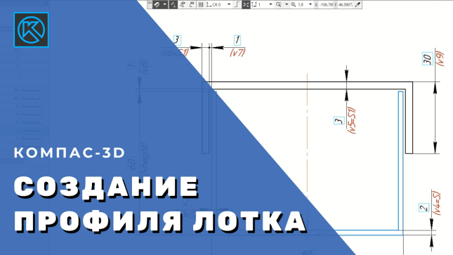
You define a cable channel profile using a fragment library. In the fragment, closed contours of parts are built: the body, the lid, and other elements. Dimensions and variable parameters are set. The contour of each part is placed on a separate layer.
Using the simulated channel, you can build a drawing and generate a specification for the subsequent order of materials.
Manufacturer: ASCON-Design SystemsLLC Requires for work: KOMPAS-3DSystem requirements correspond to KOMPAS-3D system requirements
Using the simulated channel, you can build a drawing and generate a specification for the subsequent order of materials.
Manufacturer: ASCON-Design SystemsLLC Requires for work: KOMPAS-3DSystem requirements correspond to KOMPAS-3D system requirements
KOMPAS 3D Application
Instrumentation
UNIT I
Four Exmples from Text Book will be given trainingOn software listed For the program Four problem will be given for self training with software to Trainee
Four Exmples from Text Book will be given trainingOn software listed For the program Four problem will be given for self training with software to Trainee
eCAD Converter – COMPASS
eCAD Converter – COMPASS
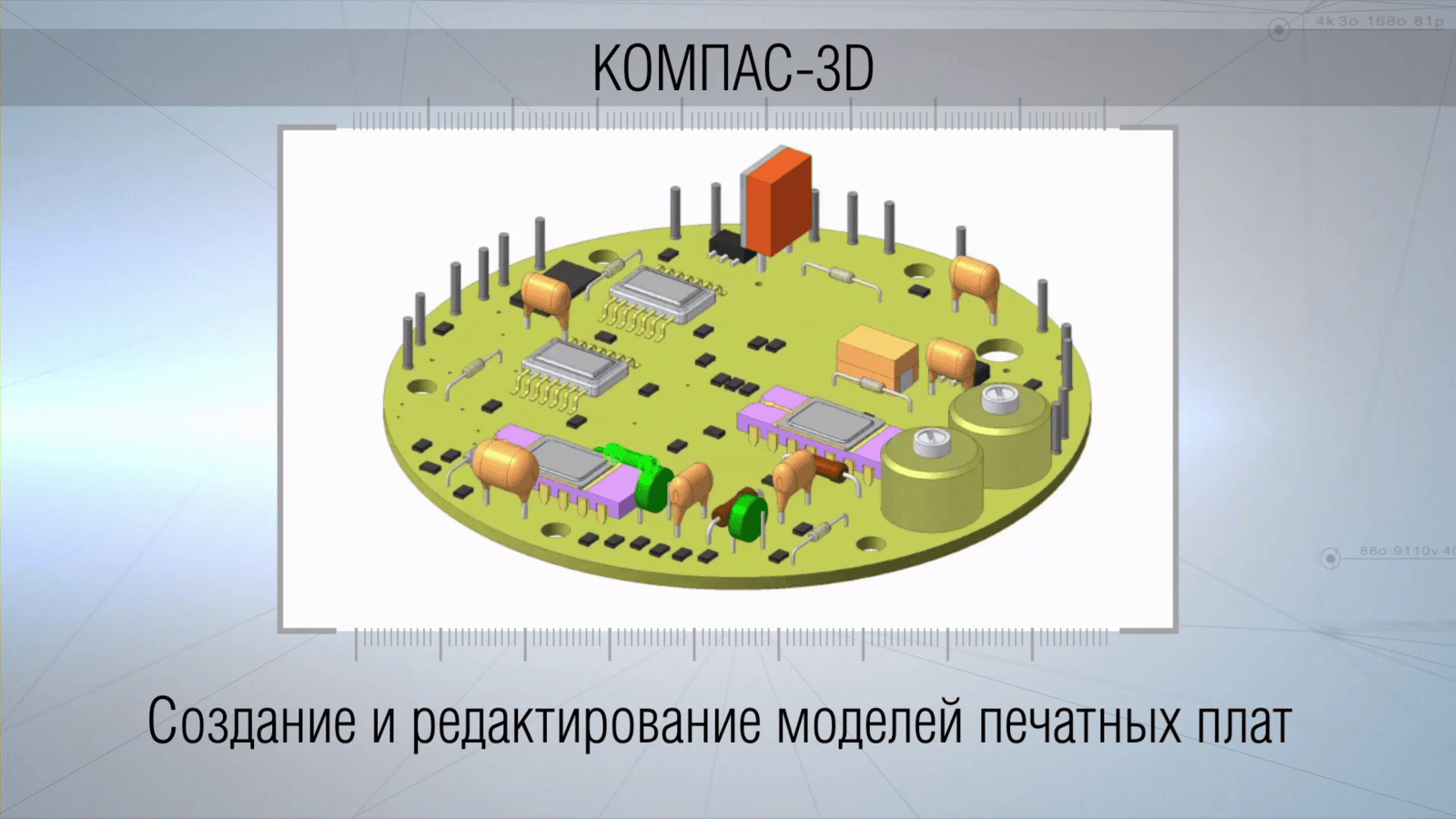
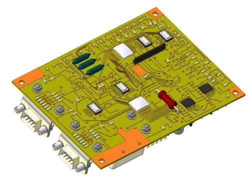
The 3D PCB Model Converter is a specialized application for obtaining a 3D model of a printed circuit board developed in ECAD systems.
UNIT II
Four Exmples from Text Book will be given trainingOn software listed For the program Four problem will be given for self training with software to Trainee
The converter allows you to read the standardized IDF data exchange format into KOMPAS-3D. The converter works with IDF files that are exported from P-CAD, OrCAD, Protel, MENTOR GRAPHICS, Altium Designer, and Cadence Allegro systems. The converter has the ability to form mounting holes in the PCB. A 3D PCB model can be presented both in a simplified form (direct import of IDF files) and in a realistic form. To get a realistic view of the board, users must prepare models of individual components in KOMPAS-3D format in advance or import models from other CAD systems with a little modification
eCAD Converter – COMPASS
eCAD Converter – COMPASS
UNIT III
Four Exmples from Text Book will be given trainingOn software listed For the program Four problem will be given for self training with software to Trainee
eCAD Converter – COMPASS
eCAD Converter – COMPASS
The text converter is designed to receive in the KOMPAS-Graph format the list of elements to the schematic specification for products developed in the P-CAD, OrCAD, Protel, Altium Designer and Cadence Allegro systems. The received documents fully comply with the ESKD and can be finalized, if necessary, by standard KOMPAS-Schedule tools.
UNIT IV
Four Exmples from Text Book will be given trainingOn software listed For the program Four problem will be given for self training with software to Trainee
eCAD Converter – COMPASS`
eCAD Converter – COMPASS`
Manufacturer: ASCON-Design SystemsLLC Requires for work: KOMPAS-3DSystem requirements correspond to KOMPAS-3D system requirements
KOMPAS 3D Application
Instrumentation
UNIT I
Four Exmples from Text Book will be given trainingOn software listed For the program Four problem will be given for self training with software to Trainee
Four Exmples from Text Book will be given trainingOn software listed For the program Four problem will be given for self training with software to Trainee
Shafts and mechanical transmissions 3D. Clock movements
Shafts and mechanical transmissions 3D. Clock movements
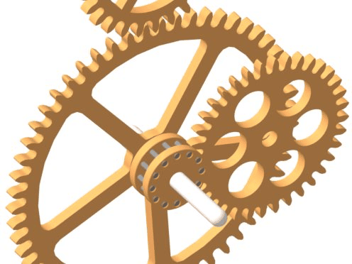
An add-on to the basic application Shafts and Mechanical Transmissions 3D for the design of time instruments.Time devices are included in many industrial systems of automated control of technological processes. They are used, for example, to control the duration of processes or signals, to record moments of current time.Watches are subject to high demands in terms of precision, reliability and reliability. The calculation methods used in the module are guaranteed to allow you to design geometrically correct gears
UNIT II
Four Exmples from Text Book will be given trainingOn software listed For the program Four problem will be given for self training with software to Trainee
The following elements of clock transmissions can be designed with the help of the module:cylindrical gears with clock profile;Wallover clock gears.The design methodology is based on:GOST 13678-73 "Small-modulus cylindrical gear gears with a clock profile. Types, Basic Parameters and Dimensions, Tolerances";RTM 31.4005-76 "Wallover transmissions. Calculation, tolerances and execution of drawings".
Shafts and mechanical transmissions 3D. Clock movements
Shafts and mechanical transmissions 3D. Clock movements
UNIT III
Four Exmples from Text Book will be given trainingOn software listed For the program Four problem will be given for self training with software to Trainee
Shafts and mechanical transmissions 3D. Clock movements
Shafts and mechanical transmissions 3D. Clock movements
For the convenience of the designer, when performing a geometric calculation, a number of parameters can be selected from a list of predefined values or tables of regulatory documents.
The calculated meshing can be visualized.
After geometrical analysis and design features in 3D Shafts and Transmissions, you can create a 3D model of the gear joint, feature drawings, build a tooth profile, and generate a parameter table
The calculated meshing can be visualized.
After geometrical analysis and design features in 3D Shafts and Transmissions, you can create a 3D model of the gear joint, feature drawings, build a tooth profile, and generate a parameter table
UNIT IV
Four Exmples from Text Book will be given trainingOn software listed For the program Four problem will be given for self training with software to Trainee
Shafts and mechanical transmissions 3D. Clock movements
Shafts and mechanical transmissions 3D. Clock movements
Manufacturer: ASCON-Design SystemsLLC Not available in KOMPAS-3D Home and KOMPAS-3D Educational version.Requires for work: "KOMPAS-3D", "Shafts and mechanical transmissions 3D"System requirements correspond to the system requirements of KOMPAS-3D
KOMPAS 3D Application
Instrumentation
UNIT I
Four Exmples from Text Book will be given trainingOn software listed For the program Four problem will be given for self training with software to Trainee
Four Exmples from Text Book will be given trainingOn software listed For the program Four problem will be given for self training with software to Trainee
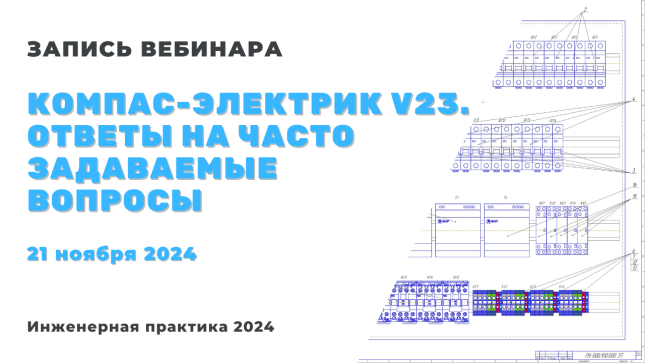
KOMPAS-Electric
KOMPAS-Electric
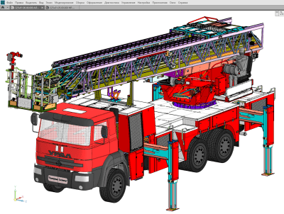
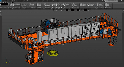
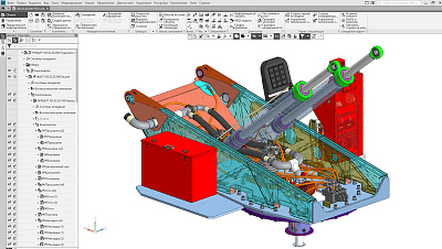
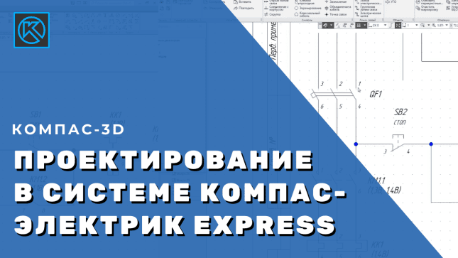
KOMPAS-Electric is a domestic application for computer-aided design of electrical equipment (CAD) for production facilities (products) that use wired installation.
The main users of the Computer Program are machine-building and instrument-making enterprises of various profiles that need to develop documentation for electrical equipment.
The app comes in two versions: KOMPAS-Electric and KOMPAS-Electric Express.
The main users of the Computer Program are machine-building and instrument-making enterprises of various profiles that need to develop documentation for electrical equipment.
The app comes in two versions: KOMPAS-Electric and KOMPAS-Electric Express.
UNIT II
Four Exmples from Text Book will be given trainingOn software listed For the program Four problem will be given for self training with software to Trainee
KOMPAS-Electric
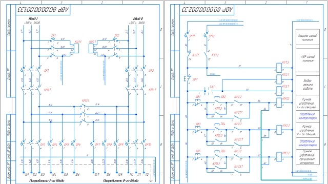
It allows you to issue a full set of design documents for electrical equipment, these are:
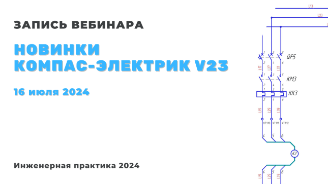
Electrical circuit diagram (E3);Diagram of electrical connections (E4);Electrical connection diagram (E5);General electrical circuit (E6);Electrical layout diagram (E7);Marking of surfaces;Specification (SP);List of purchased products (VP);List of elements (PE);Table of connections (TE4);Table of connections (TE5);General table (TE6);Table of inscriptions.
A special module included in KOMPAS-Electric allows you to add your own tabular and text documents that are different from the built-in ones.
It allows you to issue a full set of design documents for electrical equipment, these are:
Electrical circuit diagram (E3);Diagram of electrical connections (E4);Electrical connection diagram (E5);General electrical circuit (E6);Electrical layout diagram (E7);Marking of surfaces;Specification (SP);List of purchased products (VP);List of elements (PE);Table of connections (TE4);Table of connections (TE5);General table (TE6);Table of inscriptions.
A special module included in KOMPAS-Electric allows you to add your own tabular and text documents that are different from the built-in ones.
KOMPAS-Electric
KOMPAS-Electric
UNIT III
Four Exmples from Text Book will be given trainingOn software listed For the program Four problem will be given for self training with software to Trainee
KOMPAS-Electric
KOMPAS-Electric
KOMPAS-Electric Express
Allows you to issue the following documents:
Electrical circuit diagram (E3);List of elements (PE).
The issuance of documentation is carried out taking into account the requirements of GOST ESKD.
Allows you to issue the following documents:
Electrical circuit diagram (E3);List of elements (PE).
The issuance of documentation is carried out taking into account the requirements of GOST ESKD.
Databases
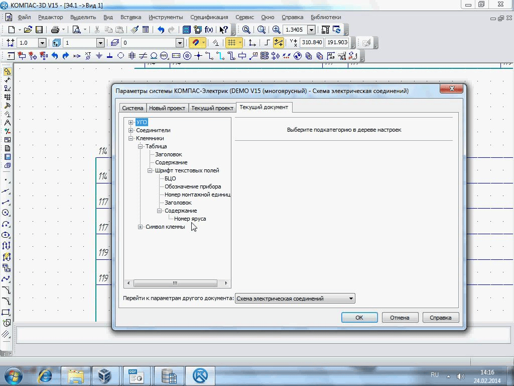
The development of the KOMPAS-Electric project is carried out using information from the database, which stores the description of components used in the projects, and their images for diagrams.
To work with the database, the user is provided with simple and intuitive tools that do not require deep knowledge of the administration of database management systems (DBMS). The database is made using client-server technology, which allows you to use unified data in projects carried out at different workplaces.
The development of the KOMPAS-Electric project is carried out using information from the database, which stores the description of components used in the projects, and their images for diagrams.
To work with the database, the user is provided with simple and intuitive tools that do not require deep knowledge of the administration of database management systems (DBMS). The database is made using client-server technology, which allows you to use unified data in projects carried out at different workplaces.
UNIT IV
Four Exmples from Text Book will be given trainingOn software listed For the program Four problem will be given for self training with software to Trainee
KOMPAS-Electric
KOMPAS-Electric
DBMS support
KOMPAS-Electric supports four types of DBMS: MS Access, MS SQL, Firebird, Oracle.
KOMPAS-Electric Express supports only MS Access DBMS.
Using the KOMPAS-Electric application allows you to:to improve the quality of the issued documentation due to the presence in the system of a large number of different control algorithms;Increase the speed of documentation release: the presence in the system of a large set of automatic actions, for example, automatic generation of tabular and text documents.
KOMPAS-Electric supports four types of DBMS: MS Access, MS SQL, Firebird, Oracle.
KOMPAS-Electric Express supports only MS Access DBMS.
Using the KOMPAS-Electric application allows you to:to improve the quality of the issued documentation due to the presence in the system of a large number of different control algorithms;Increase the speed of documentation release: the presence in the system of a large set of automatic actions, for example, automatic generation of tabular and text documents.
Instrumentation - Construction
KOMPAS 3D Application
Instrumentation
UNIT I
Four Exmples from Text Book will be given trainingOn software listed For the program Four problem will be given for self training with software to Trainee
Four Exmples from Text Book will be given trainingOn software listed For the program Four problem will be given for self training with software to Trainee
KOMPAS-Electric Express
KOMPAS-Electric Express
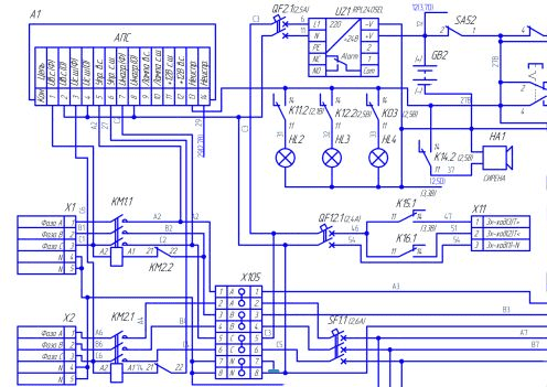
KOMPAS-Electric Express is intended for users who are engaged in the development of schematic diagrams and lists of elements for them. This option is significantly simplified in relation to KOMPAS-Electric.
Instrumentation - Construction
UNIT II
Four Exmples from Text Book will be given trainingOn software listed For the program Four problem will be given for self training with software to Trainee
The KOMPAS-Electric Express application includes:
A project manager that navigates between project documents;The Schematic and Report Editor, in which these documents are developed and issued;Database of components and symbols.
A project manager that navigates between project documents;The Schematic and Report Editor, in which these documents are developed and issued;Database of components and symbols.
KOMPAS-Electric Express
KOMPAS-Electric Express
n terms of schematic diagram and element list functions, KOMPAS-Electric Express has the same capabilities as KOMPAS-Electric. These are:
I
I
Inserting the UGO from the Library into the schematic;Insert additional symbols on the communication line;the ability to expand the Library's nomenclature by the user;construction of electric communication lines, group communication line, electric bus;automatic arrangement of wire markings;automatic generation of a list of elements;
UNIT III
Four Exmples from Text Book will be given trainingOn software listed For the program Four problem will be given for self training with software to Trainee
KOMPAS-Electric Express
KOMPAS-Electric Express
n terms of schematic diagram and element list functions, KOMPAS-Electric Express has the same capabilities as KOMPAS-Electric. These are:
Combining graphically unrelated electrical communication lines into a single potential node (both within and between sheets)depicting one element on the diagram in a spaced way;Entering elements into the database directly while working on the diagram and their further use in other projects;Adding 3D models and text documents to the projectexport of documents to KOMPAS-Graphic.
UNIT IV
Four Exmples from Text Book will be given trainingOn software listed For the program Four problem will be given for self training with software to Trainee
KOMPAS-Electric Express
KOMPAS-Electric Express
Manufacturer: ASCON-Design SystemsLLC Not available in KOMPAS-3D Home.Requires for work: "KOMPAS-3D" or "KOMPAS-Graphic"System requirements correspond to the system requirements of KOMPAS-3D