Industry Projects
Construction Projects
RCC Structure Five Stored Brick
Internship Program-Project Program-Product Dev, Program


UNIT III
Four Exmples from Text Book will be given trainingOn software listed For the program Four problem will be given for self training with software to Trainee
The weight of floor coverings, thermal insulation, fittings, welds, etc., is given by introducing a self-weight factor > 1. To determine the self-weight multiplier, the proportion of unaccounted weight in the constructed structural model was determined. The largest share falls on the floor covering with ceramic tiles.
A steel plate of equivalent thickness was used to model the metal tiles.
To model the window and balcony openings, plates without stiffness with equivalent thickness (material glass) were used, which transmit wind loads and dead weight to the supporting structures.
The rafter system and the metal structure are a single structure and take the load together, which allows you to ensure an even distribution of forces between the structural elements.
For the analysis of natural frequencies, a complex structure consisting of a reinforced concrete frame with brick filling was used.
Calculation results
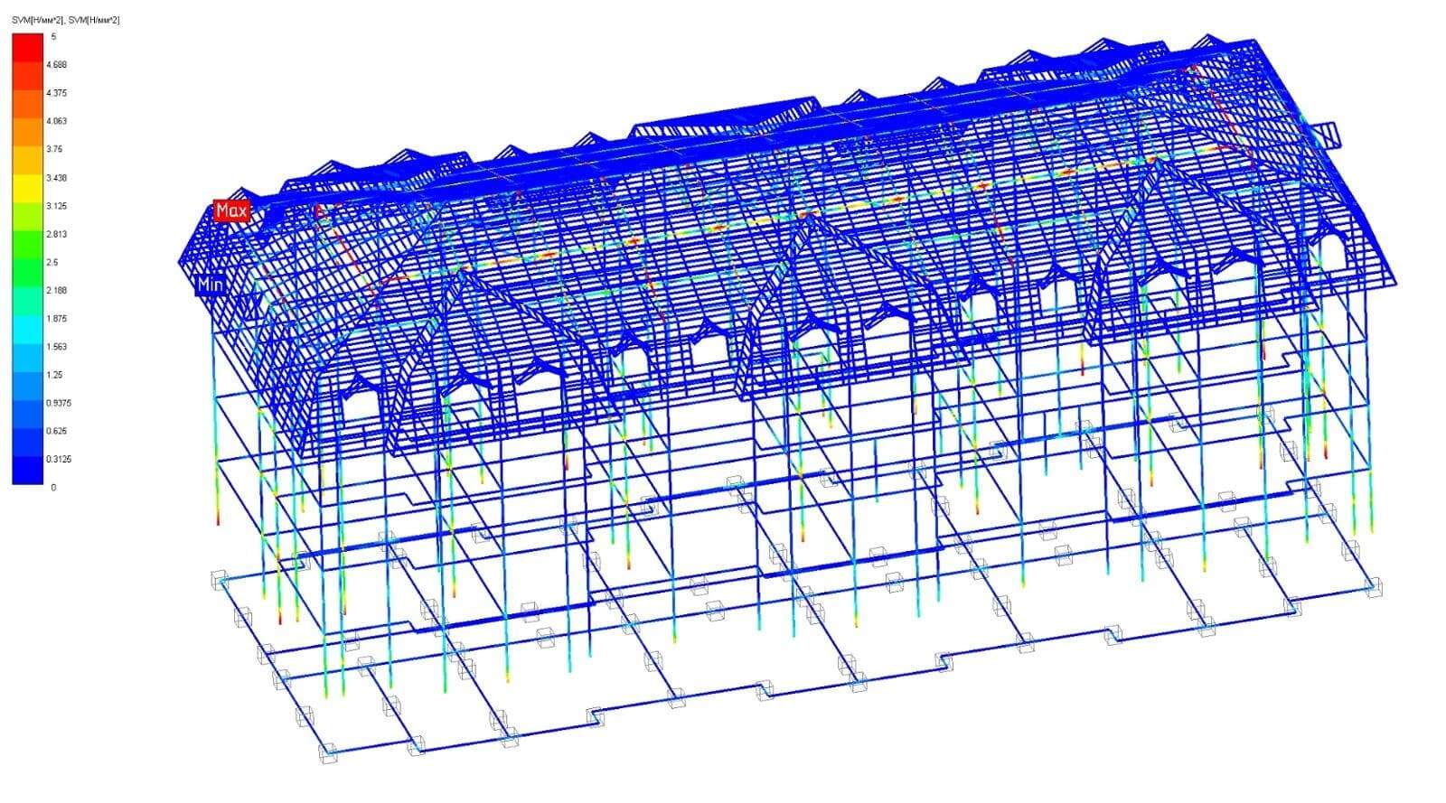
The maximum stresses are caused by the combination of load cases with seismic loading.
Rebar utilization factors are less than 1. It can be concluded that the reinforcement used provides strength in the first and second groups of limit states.
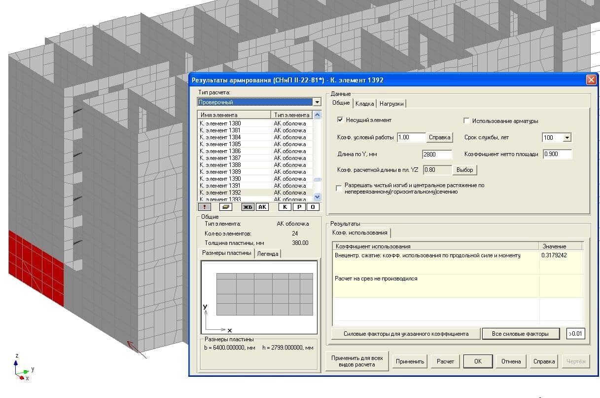
The calculation of stone structural elements was carried out in accordance with SNiP II-22-81*. For all structural elements, the utilization factors are less than 1. Therefore, the condition of strength of brick walls is met. Design reinforcement of masonry structural elements is not required.
Even assuming that all the load is absorbed by the base of the pile, the bearing capacity is higher than the maximum acting capacity on the pile.
UNIT I
Four Exmples from Text Book will be given trainingOn software listed For the program Four problem will be given for self training with software to Trainee
The calculation was carried out by order of ChernomorStroyProekt LLC.
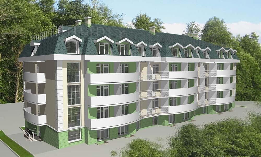
The construction of the building is planned in the village of Novomikhailovsky, Tuapse district.
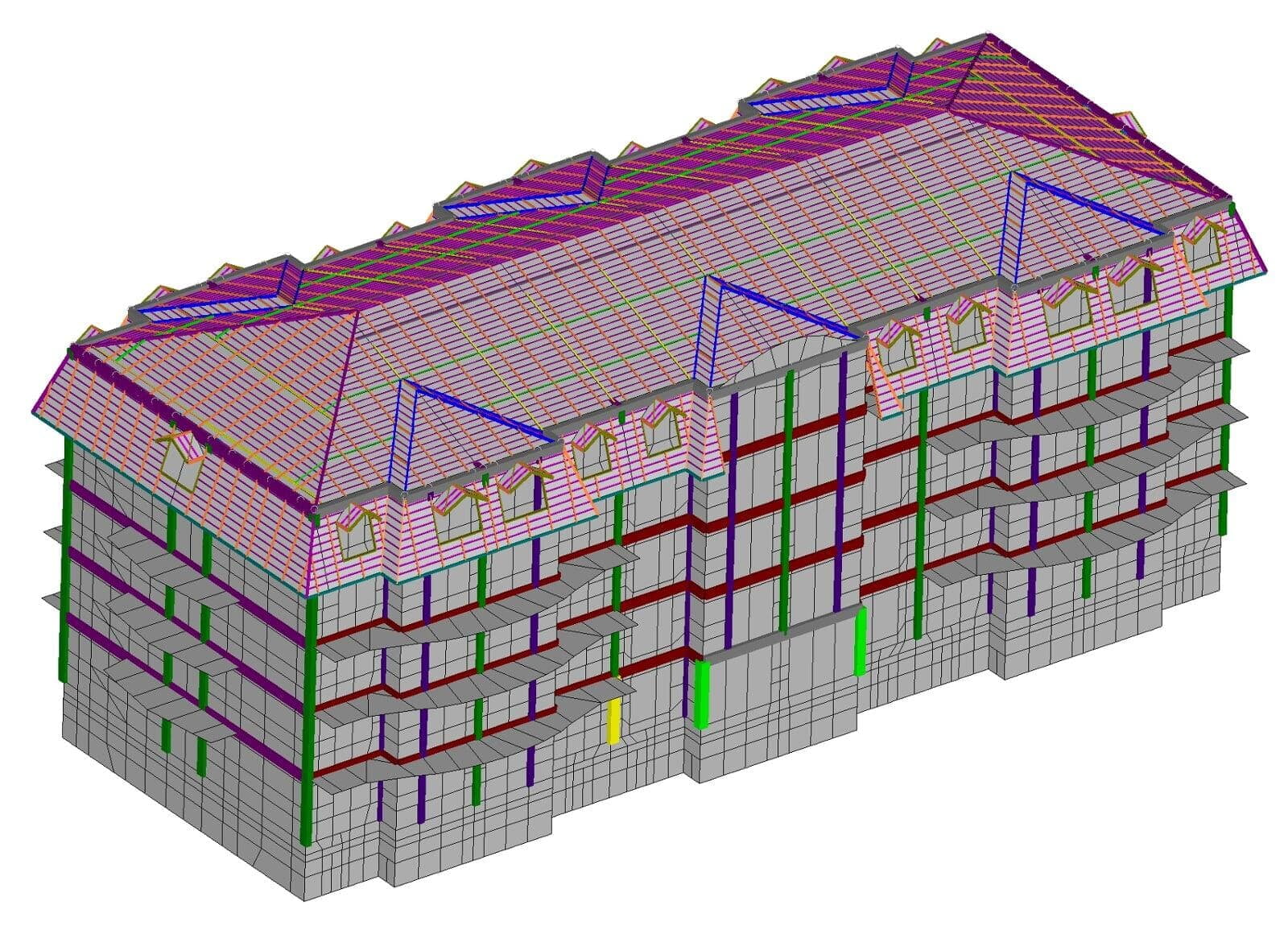
The building consists of two parts: a roof made of metal structure and a brick building with reinforced concrete inclusions. The walls of the technical basement are monolithic reinforced concrete 500, 400, 300 mm made of B10 class concrete. The walls of the building are made of clay fired bricks. Floor slabs are monolithic reinforced concrete with a thickness of 160 mm made of B20 class concrete. The partitions inside the building are brick with a thickness of 120 and 65 mm. The roof of the building is gable with rafters made of boards (pine) laid on a steel frame.
The calculation was carried out in accordance with the current regulatory documents:
SNiP 2.01.07-85* Loads and impacts;SNiP II-7-81* Construction in seismic areas;SNKK 20-303-2002 Loads and Impacts, Wind and Snow Loads (TSN 20-302-2002 of the Krasno-Darsky Territory);SP 31-114-2004 Rules for the design of residential and public buildings for construction in seismic areas;SNiP II-22-81* Stone and reinforced masonry structures;Reference Manual for SNiP 2.09.03-85* Design of Retaining Walls and Basement Walls;SP 50-102-2003 Design and installation of pile foundations;SP 52-101-2003 Concrete and reinforced concrete structures without prestressing reinforcement.
The calculation was carried out in the APM CivilEngineering software product.
UNIT IV
Four Exmples from Text Book will be given trainingOn software listed For the program Four problem will be given for self training with software to Trainee
The reinforcement used provides strength in the first and second groups of limit states.
For all structural elements, the utilization factors are less than one. Therefore, the condition of strength of brick walls is met.
In accordance with SP 50-102-2003 "Design and Installation of Pile Foundations", the calculation of piles was carried out, the results of which showed that the bearing capacity of the pile-rack in terms of soil and material is ensured, and the piles are calculated for the combined action of vertical and horizontal forces and moment and the action of shear force.
The work carried out showed the applicability of the APM Civil Engineering software package for solving complex problems of strength analysis of reinforced concrete structures.
UNIT II
Four Exmples from Text Book will be given trainingOn software listed For the program Four problem will be given for self training with software to Trainee
Input
The model of the building structure is created in accordance with the customer's drawings.
Loads were set in accordance with SNiP 2.01.07-85* and SNKK 20-303-2002.
The following types of loads were identified:
Constant loads
- Dead weight;
- Weight of bathroom partitions.
The weight of floor coverings, thermal insulation, fittings, welds, etc. will be set by entering the self-weight factor. The largest share (see Table 1) falls on the floor covering with ceramic tiles.
Constant loads from soil pressure on the walls of the technical basement
The backfill soil pressure acts on the walls of the technical underground. The soil pressure on the wall varies according to a linear law depending on the depth from 0 to the calculated maximum value.
Short-term loads
This type of load was determined in accordance with SNiP 2.01.07-85* depending on the element:
- Attic rooms;
- Balconies;
- On the floor slabs of living rooms;
- Service premises: utility rooms (kitchens, showers, lavatories);
- Corridors, lobbies, stairs.
Snow loads
Snow loads were determined according to SNiP 2.01.07-85* for the I snow region.
Wind loads
Wind loads were determined according to SNiP 2.01.07-85* for the III wind region. The wind direction was taken along the largest surface of the building, which also corresponds to the lowest stiffness of the building and is the worst case.
Seismic Loads
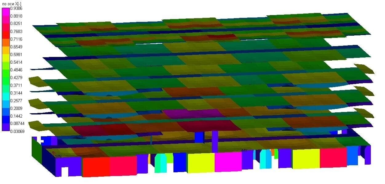
Taking into account that the rigidity of individual structural elements (roof structural elements, cantilever balcony slabs, etc.) is much less than the load-bearing walls of the structure, the calculation of natural frequencies and vibration shapes was carried out for flat frames. Since the rigidity of the building frames along the numerical axes is much less than the rigidity along the letter axes, let's perform the calculation along the characteristic axes.