Industry Projects
Construction Projects
Structural Steel Chimeny Structure
Internship Program-Project Program-Product Dev, Program


UNIT I
Four Exmples from Text Book will be given trainingOn software listed For the program Four problem will be given for self training with software to Trainee
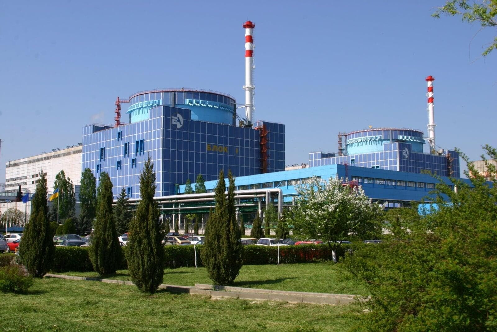
The calculation of the NPP chimney was carried out by order of the Khmelnytsky NPP.
The chimney is located on the reinforced concrete slab covering the structure of the reactor compartment of the NPP. The design of a ventilation pipe is to place one pipe inside another, using the space between them as a ventilation shaft.
The outer pipe with a diameter of 3 m and a wall thickness of 16 mm is the load-bearing structure. The inner pipe with a diameter of 1.6 m and a wall thickness of 4 mm is suspended from the outer one. Fastening of the inner pipe to the outer pipe is carried out by four ribs 10 mm thick, installed along the pipes with a step of 10 m. Pipes are made of 15KHSND steel.
The design analysis was performed in the APM CivilEngineering software product.
UNIT IV
Four Exmples from Text Book will be given trainingOn software listed For the program Four problem will be given for self training with software to Trainee
The calculation for the seismic effects of the ventilation pipe was performed.
From the results of the calculations performed, it follows that the strength of the ventilation pipe elements under seismic effects is ensured in accordance with the requirements of regulatory documents.

UNIT II
Four Exmples from Text Book will be given trainingOn software listed For the program Four problem will be given for self training with software to Trainee
The following documents provided by the Customer were accepted as initial data for performing calculations for seismic effects of the ventilation pipe:
working drawings;conclusion on the results of the inspection of building structures;the results of engineering and geological surveys of the site.
Calculation model
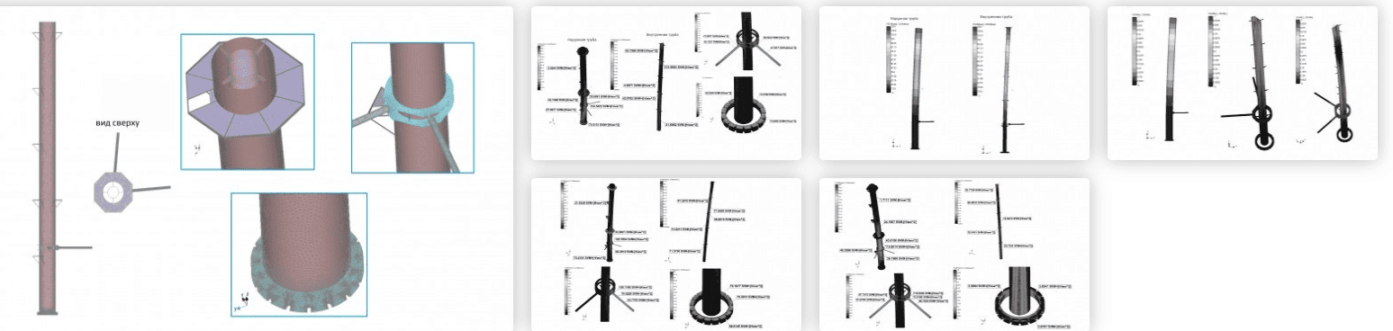
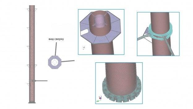
The design model of the ventilation pipe is built in accordance with the working drawings received from the Customer.
When building the calculation model for the internal and external ventilation pipes, as well as for the struts and fins, three-node plate finite elements were used. When building the struts and beams of the landings, rod finite elements were used.
Loads acting on the ventilation pipe:
the own weight of load-bearing structures;tightening of foundation bolts;load from people;wind load;seismic impacts.
Kinematic boundary conditions are set in the form of rigid pinching of the ventilation pipe nodes at the point of its support on the reinforced concrete coating of the outbuilding, as well as in the form of hinged fastening of the nodes at the place where the struts support the protective shell.
UNIT III
Four Exmples from Text Book will be given trainingOn software listed For the program Four problem will be given for self training with software to Trainee
The calculation for seismic effects was carried out by the linear-spectral method using the spectra of horizontal and vertical accelerations.
The natural frequencies and the corresponding vibration shapes of the ventilation pipe were determined by the finite element method.
Based on the results of the calculation, the reduced (according to Mises) stresses and total displacements were determined. The calculation of the integral seismic stability parameter HCLPF is carried out.