Industry Projects
Mechanical Projects NPP equipment
Plant Piping
Internship Program-Project Program-Product Dev, Program

APM WINMACHINE APM CIVIL APM FEM

UNIT I
Four Exmples from Text Book will be given trainingOn software listed For the program Four problem will be given for self training with software to Trainee
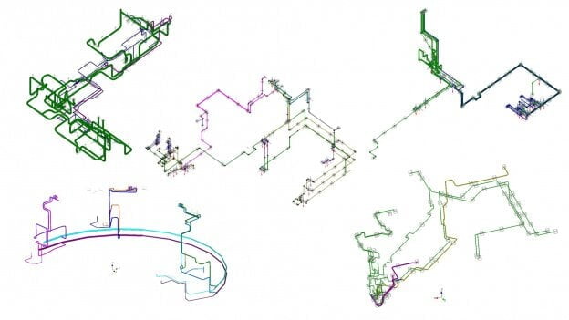
Nuclear Power Plant Pipelines
The calculation of the pipelines was carried out by order of the Balakovo Nuclear Power Plant, a branch of Rosenergoatom Concern OJSC.
The calculation of NPP piping systems is carried out in accordance with the requirements of:
PNAE G-7-002-86 "Strength Design Standards for Equipment and Pipelines of Nuclear Power Plants";RD EO 1.1.2.05.0330-2012 "Guidelines for Strength Analysis of Equipment and Work Pipelines of RBMK, VVER and EPG Reactor Plants at the Operating Station, Including Operation Beyond the Design Service Life";PNAE G-7-008-89 "Rules for the Construction and Safe Operation of Equipment and Pipelines of Nuclear Power Plants".
As part of the verification calculation, the following types of calculations must be performed:
Static strength calculation;calculation for cyclic strength;seismic analysis.
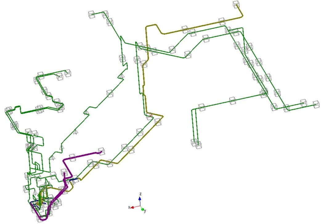
The calculation of pipelines was carried out in the APM WinMachine software package. During the construction, a special type of rod elements was used - a pipe (Pipe). As properties, this element allows you to set the density of the internal medium and insulation material, the thickness of the insulation layer and permissible corrosion, as a load - internal or external pressure.
The calculation of the pipelines was carried out by order of the Balakovo Nuclear Power Plant, a branch of Rosenergoatom Concern OJSC.
The calculation of NPP piping systems is carried out in accordance with the requirements of:
PNAE G-7-002-86 "Strength Design Standards for Equipment and Pipelines of Nuclear Power Plants";RD EO 1.1.2.05.0330-2012 "Guidelines for Strength Analysis of Equipment and Work Pipelines of RBMK, VVER and EPG Reactor Plants at the Operating Station, Including Operation Beyond the Design Service Life";PNAE G-7-008-89 "Rules for the Construction and Safe Operation of Equipment and Pipelines of Nuclear Power Plants".
As part of the verification calculation, the following types of calculations must be performed:
Static strength calculation;calculation for cyclic strength;seismic analysis.
The calculation of pipelines was carried out in the APM WinMachine software package. During the construction, a special type of rod elements was used - a pipe (Pipe). As properties, this element allows you to set the density of the internal medium and insulation material, the thickness of the insulation layer and permissible corrosion, as a load - internal or external pressure.
UNIT IV
Four Exmples from Text Book will be given trainingOn software listed For the program Four problem will be given for self training with software to Trainee
Results of the completed project
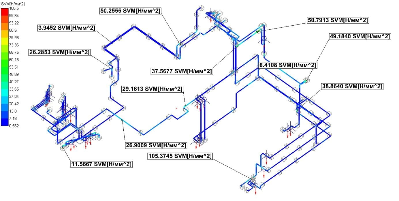
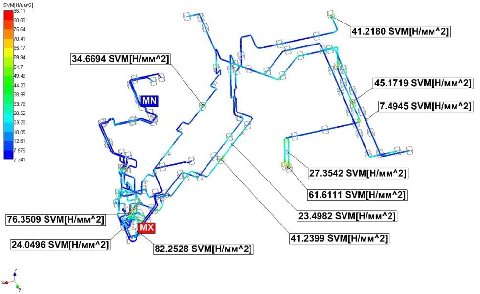
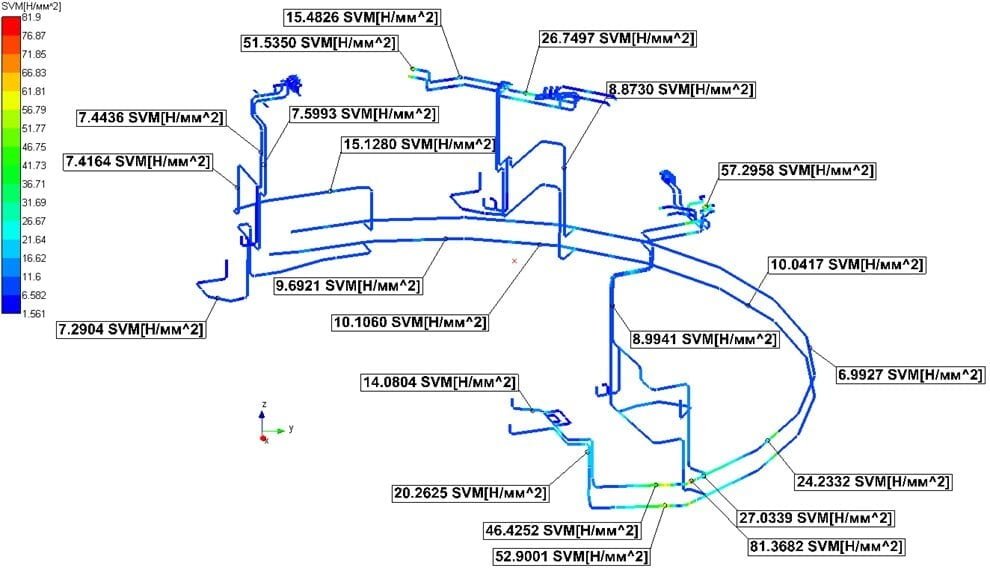
The stresses in the pipelines do not exceed the permissible ones. Thus, the conditions of static strength of pipelines are met in accordance with the requirements of PNAE G-7-002-86.
From the results of the calculations, we obtain that the maximum accumulated fatigue damage in the pipelines does not exceed the permissible values.
Strength under seismic effects is provided in accordance with PNAE G-7-002-86.
The results obtained show that the APM WinMachine system for performing complex engineering analysis of mechanical equipment and structures can be used for pipeline calculations.
The stresses in the pipelines do not exceed the permissible ones. Thus, the conditions of static strength of pipelines are met in accordance with the requirements of PNAE G-7-002-86.
From the results of the calculations, we obtain that the maximum accumulated fatigue damage in the pipelines does not exceed the permissible values.
Strength under seismic effects is provided in accordance with PNAE G-7-002-86.
The results obtained show that the APM WinMachine system for performing complex engineering analysis of mechanical equipment and structures can be used for pipeline calculations.

UNIT II
Four Exmples from Text Book will be given trainingOn software listed For the program Four problem will be given for self training with software to Trainee
alculation model
When building the design model of the pipeline, the finite element "Pipe" was used.
Force boundary conditions are defined as:
the pipeline's own weight;internal pressure;temperature along the length of the pipeline.
When building the design model of the pipeline, the finite element "Pipe" was used.
Force boundary conditions are defined as:
the pipeline's own weight;internal pressure;temperature along the length of the pipeline.
UNIT III
Four Exmples from Text Book will be given trainingOn software listed For the program Four problem will be given for self training with software to Trainee
Kinematic boundary conditions are defined in the form of the following types of supports, placed in accordance with the as-built schemes provided by the Customer:
rigid supports (exclude all displacements and angles of rotation of the pipeline section);fixed supports (exclude all movements of the pipeline section);guide supports (excludes vertical movement and movement perpendicular to the direction of the pipeline);sliding supports (exclude vertical movement of the pipeline section).
The geometric characteristics of the pipeline sections are set in accordance with the drawings provided by the Customer.
Valves, valves, gate valves are set using a special command - pipeline valves.
rigid supports (exclude all displacements and angles of rotation of the pipeline section);fixed supports (exclude all movements of the pipeline section);guide supports (excludes vertical movement and movement perpendicular to the direction of the pipeline);sliding supports (exclude vertical movement of the pipeline section).
The geometric characteristics of the pipeline sections are set in accordance with the drawings provided by the Customer.
Valves, valves, gate valves are set using a special command - pipeline valves.
Calculation results
Static Strength Analysis by Stress Category Groups (σ)1 and (σ)2 It is performed for pipeline elements loaded with internal pressure and dead weight. When checking static strength by groups of stress categories (σ)RK Stress ranges from internal pressure, self-weight, and temperature stresses are taken into account.
When calculating the cyclic strength, all possible design modes were taken into account. The number of cycles for a certain period of operation is provided by the Customer.
Seismic loads were determined using generalized response spectra. The calculation for seismic effects was carried out by the linear-spectral method.
Static Strength Analysis by Stress Category Groups (σ)1 and (σ)2 It is performed for pipeline elements loaded with internal pressure and dead weight. When checking static strength by groups of stress categories (σ)RK Stress ranges from internal pressure, self-weight, and temperature stresses are taken into account.
When calculating the cyclic strength, all possible design modes were taken into account. The number of cycles for a certain period of operation is provided by the Customer.
Seismic loads were determined using generalized response spectra. The calculation for seismic effects was carried out by the linear-spectral method.